Discrete Varying Delay
Discrete varying delay with support for fixed delay and zero delay (direct feedthrough)
Since R2024a

Libraries:
Control System Toolbox /
Linear Parameter Varying
Description
The Discrete Varying Delay block extends the functionality of the Variable Integer Delay (Simulink) block in the Simulink /
Discrete library by providing additional support for specifying fixed and
zero delays. This block is helpful when you want to model a mix of zero, fixed, and varying
delays, which can occur in LPV models.
Examples
This example shows how to use the Discrete Varying Delay block provided with the Control System Toolbox™ library. This block is useful when you want to model fixed, varying, and zero delays for individual channels in the signal using just one block.
Open the model provided with this example.
mdl = "DiscreteVarDelayModel";
open_system(mdl)
This model contains a ramp source connected to a Rate Transition block to generate a 3-by-1 discrete signal with sample time 0.2 s. The ramp signals have a slope of 1, 2, and 3 at the corresponding indices. The Sine Wave block generates a signal for the varying delay port.
For this model, specify:
A varying delay with a nominal delay of 1 s (5 samples) in the first channel of the ramp signal. The instantaneous value of the varying delay value is provided by the Sine Wave block. When the varying delay output is noninteger, the block rounds the delay value to the nearest integer.
A fixed delay of 3 s (15 samples) in the second channel of the ramp signal.
A zero delay (feedthrough) for the third channel of the ramp signal.
Configure the block parameters as shown.

Specify the nominal delay parameter as a vector with values 5, 15, and 0 corresponding to the delays (in samples) in each channel. Use the Fixed delays (indices) parameter to specify fixed delays for channels 2 and 3.
Examine the structure under the block mask. The block automatically configures the delays based on the specified settings. The varying delay length input has a Saturation block to ensure that the delay is nonnegative. Therefore, it provides a value of 0 when sin(k*Ts) becomes negative. The block also rounds any noninteger input values to the nearest integer value.

Run the model and view the result.
sim(mdl);
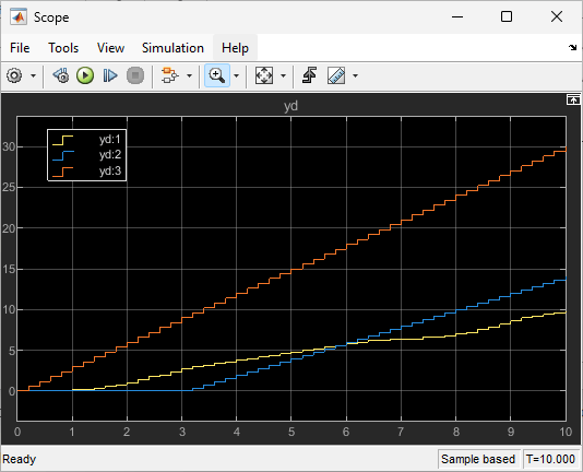
As you can see, the first channel has a varying delay, the second channel has a fixed delay of 3 s (15 samples), and the third channel has zero delay.
close_system(mdl)
Ports
Input
Output
Parameters
Extended Capabilities
Version History
Introduced in R2024a