Hauptinhalt

Discrete Varying Observer Form

R2026b

Discrete-time observer-form state-space model with varying matrix values

  • Discrete Varying Observer Form block

Libraries:
Control System Toolbox / Linear Parameter Varying

Description

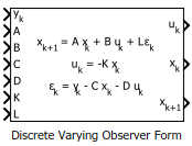
Use this block to implement a discrete-time varying state-space model in observer form. The system matrices A, B, C, and D describe the plant dynamics, and the matrices K and L specify the state-feedback and state-observer gains, respectively. Feed the instantaneous values of these matrices to the corresponding input ports. The observer form is given by:

xk+1=Axk+Buk+Lεkuk=−Kxkεk=yk−Cxk−Duk,

where uk is the plant input (control signal), yk is the plant output, xk is the estimated state, and εk is the innovation, the difference between the predicted and measured plant output. The observer form works well for gain scheduling of state-space controllers. In particular, the state xk tracks the plant state, and all controllers are expressed with the same state coordinates.

Use this block and the other blocks in the Linear Parameter Varying library to implement common control elements with variable parameters or coefficients. For more information, see Model Gain-Scheduled Control Systems in Simulink.

Caution

Avoid making the K matrix depend on the control signal uk. If you have such dependence, the resulting equation uk = –K(uk)xk creates an algebraic loop, because computing the block output value requires knowing the block output value. This algebraic loop is prone to instability and divergence. Instead, try expressing K in terms of the time t and the block input yk.

For similar reasons, avoid making A, B, or L depend on the uk+1 output.

Ports

Input

expand all

Measured plant output signal.

Plant state matrix of dimensions Nx-by-Nx, where Nx is the number of plant states.

Plant input matrix of dimensions Nx-by-Nu, where Nu is the number of plant inputs.

Plant output matrix of dimensions Ny-by-Nx, where Ny is the number of plant outputs.

Plant feedforward matrix of dimensions Ny-by-Nu.

State-feedback matrix of dimensions Nu-by-Nx.

State-observer matrix of dimensions Nx-by-Ny.

Since R2026b

Initial conditions of the estimated states, specified as a vector of length equal to the number of states.

Dependencies

To enable this port, set Initial condition source to external.

Since R2026b

External reset signal. When the reset signal triggers, the block resets the states to the initial conditions. To specify which signal behavior triggers a reset, use the External reset parameter.

Dependencies

To enable this port, set External reset to a value other than None.

Output

expand all

Control signal (plant input).

Vector of estimated plant states.

Dependencies

To enable this port, select the Output states parameter.

Estimated state values at next time step.

Dependencies

To enable this port, select the Output state updates parameter.

Parameters

expand all

Since R2026b

Specify the initial condition source.

  • internal — Specify the initial conditions of the states using the Initial conditions parameter.

  • external — Specify the initial conditions of the states at the IC input port of the block.

Programmatic Use

To set the block parameter value programmatically, use the set_param (Simulink) function.

Parameter: InitialConditionSource
Values: "internal" (default) | "external"

Initial state values, specified as a scalar or a vector whose length is the number of plant states.

Dependencies

To enable this parameter, set Initial condition source to internal.

Programmatic Use

To set the block parameter value programmatically, use the set_param (Simulink) function.

Parameter: InitialCondition
Values: "0" (default) | initial state values in quotes

Example: set_param(gcb,"InitialCondition","[0 0.1]")

Since R2026b

Reset the block states to the initial conditions when a trigger event occurs at the Reset input port. Selecting an option other than None enables the Reset port.

  • None — Do not reset the states.

  • Rising — Reset the states when the reset signal rises from a negative or zero value to a positive value, or from a negative value to zero.

  • Falling — Reset the states when the reset signal falls from a positive or zero value to a negative value, or from a positive value to zero.

  • Either — Reset the states when the reset signal rises or falls.

  • Level — Reset the states when the reset signal is nonzero at the current time step or changes from nonzero at the previous time step to zero at the current time step.

  • Level hold — Reset the states when the reset signal is nonzero at the current time step.

Programmatic Use

To set the block parameter value programmatically, use the set_param (Simulink) function.

Parameter: ExternalReset
Values: "None" (default) | "Rising" | "Falling" | "Either" | "Level" | "Level hold"

Example: set_param(gcb,"ExternalReset","Rising")

Block sample time, specified as either –1 (inherited sample time) or a positive scalar value.

Select to enable the estimated states output port, xe.

Select to enable the estimated state updates output port, xk+1.

Programmatic Use: Add Block

To add the block programmatically, use the add_block function with one of these library block paths as the source.

"cstblocks/Linear Parameter Varying/Discrete Varying Observer Form"

Example: add_block("cstblocks/Linear Parameter Varying/Discrete Varying Observer Form","myModel/myBlock",MakeNameUnique="on")

For information about programmatic access to individual block parameters, see the Programmatic Use section of parameter descriptions on this page.

Extended Capabilities

expand all

C/C++ Code Generation
Generate C and C++ code using Simulink® Coder™.

Version History

Introduced in R2017b

expand all