M-PSK Demodulator Baseband
Demodulate PSK-modulated data
Libraries:
Communications Toolbox /
Modulation /
Digital Baseband Modulation /
PSK
Communications Toolbox HDL Support /
Modulation /
PM
Description
The M-PSK Demodulator Baseband block demodulates a baseband representation of a PSK-modulated signal. The modulation order, M, is equivalent to the number of points in the signal constellation and is determined by the M-ary number parameter. The block accepts scalar or column vector input signals.
Examples
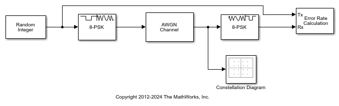
Generate and demodulate a noisy 8-PSK signal.
Open the doc_8psk_model model. The model generates random data using the Random Integer Generator block. To modulate the random data, the model uses the M-PSK Modulator Baseband block with a modulation order of 8 and a constellation order set to Gray. Subsequently, the modulated data passes through an additive white Gaussian noise channel (AWGN Channel block). The model displays the noisy constellation through the Constellation Diagram block. To demodulate this noisy signal, it employs the M-PSK Demodulator Baseband block with the same modulation and constellation order as the modulator. Finally, the model computes the error statistics using the Error Rate Calculation.
Run the model.
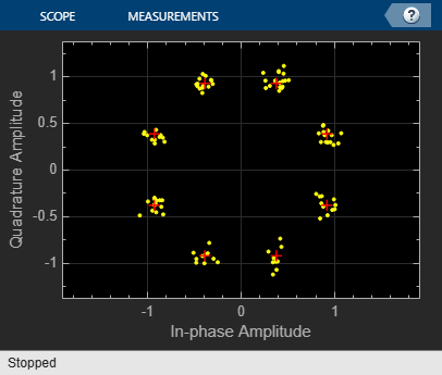
Collect the error statistics in a vector, ErrorVec. Observe that the number of symbol errors is zero when Eb/No is 15 dB.
Number of symbol errors = 0
Change the Eb/No of the AWGN Channel block from 15 dB to 5 dB. The constellation diagram shows the increase in the noise.
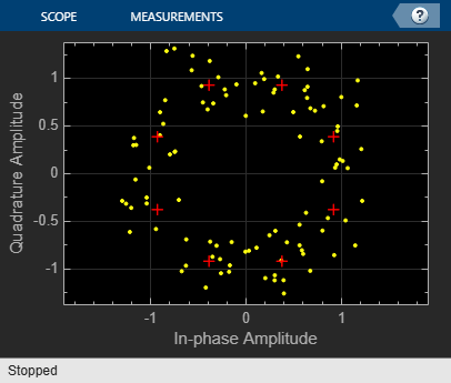
Because of the increase in the noise level, the number of symbol errors is greater than zero.
Number of symbol errors = 21
This example uses the doc_gray_code to compute bit error rates (BER) and symbol error rates (SER) for M-PSK modulation. The theoretical error rate performance of M-PSK modulation in AWGN is compared to the error rate performance for Gray-coded symbol mapping and to the error rate performance of binary-coded symbol mapping.

The Random Integer Generator block serves as the source, producing a sequence of integers. The Integer to Bit Converter block converts each integer into a corresponding binary representation. The M-PSK Modulator Baseband block in the doc_gray_code model:
Accepts binary-valued inputs that represent integers in the range [0, (M - 1], where M is the modulation order.
Maps binary representations to constellation points using a Gray-coded ordering.
Produces unit-magnitude complex phasor outputs, with evenly spaced phases in the range [0, (2
 (M - 1) / M)].
The AWGN Channel block adds white Gaussian noise to the modulated data. The M-PSK Demodulator Baseband block demodulates the noisy data. The Bit to Integer Converter block converts each binary representation to a corresponding integer. Then two separate Error Rate Calculation blocks calculate the error rates of the demodulated data. The block labeled SER Calculation compares the integer data to compute the symbol error rate statistics and the block labeled BER Calculation compares the bits data to compute the bit error rate statistics. The output of the Error Rate Calculation block is a three-element vector containing the calculated error rate, the number of errors observed, and the amount of data processed.
To reduce simulation run time and ensure that the statistics of the errors remain stable as the Eb/N0 ratio increases, the model is configured to run until 100 errors occur or until 1e8 bits have been transmitted.
The model initializes variables used to configure block parameters by using the PreLoadFcn callback function. For more information, see Model Callbacks (Simulink).
Produce Error Rate Curves
Compute the theoretical BER for nondifferential 8-PSK in AWGN over a range of Eb/N0 values by using the berawgndoc_gray_code model with Gray-coded symbol mapping over the same range of Eb/N0 values.
Compare Gray coding with binary coding, by modifying the M-PSK Modulator Baseband and M-PSK Demodulator Baseband blocks to set the Constellation ordering parameter to Binary instead of Gray. Simulate the doc_gray_code model with binary-coded symbol mapping over the same range of Eb/N0 values.
Plot the results by using the semilogy function. The Gray-coded system achieves better error rate performance than the binary-coded system. Further, the Gray-coded error rate aligns with the theoretical error rate statistics.

Ports
Input
Output
Parameters
Block Characteristics
More About
The Data Type Assistant helps you set data
attributes. To use the Data Type Assistant, click ![]() . For more information, see Specify Data Types Using Data Type Assistant (Simulink).
. For more information, see Specify Data Types Using Data Type Assistant (Simulink).
Algorithms
The signal preprocessing required for BPSK demodulation depends on the configuration.
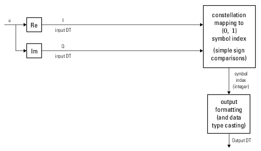
This figure shows the hard-decision BPSK demodulation signal diagram for the trivial phase offset (multiple of π/2) configuration.
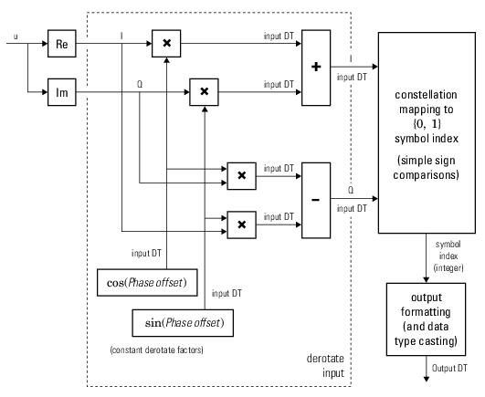
This figure shows the hard-decision BPSK demodulation floating-point signal diagram for the nontrivial phase offset configuration.
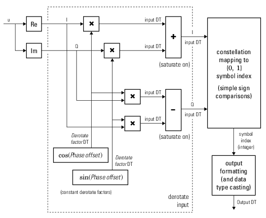
This figure shows the hard-decision BPSK demodulation fixed-point signal diagram for the nontrivial phase offset configuration.
The signal preprocessing required for QPSK demodulation depends on the configuration.
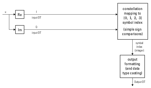
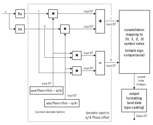
This figure shows the hard-decision QPSK demodulation signal diagram for the trivial phase offset (odd multiple of π/4) configuration.
This figure shows the hard-decision QPSK demodulation floating-point signal diagram for the nontrivial phase offset configuration.
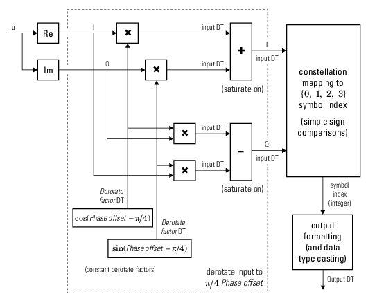
This figure shows the hard-decision QPSK demodulation fixed-point signal diagram for the nontrivial phase offset configuration.
The signal preprocessing required for higher order PSK demodulation depends on the configuration.
This figure shows the hard-decision 8-PSK demodulation signal diagram for the trivial phase offset (odd multiple of π/8) configuration.

This figure shows the hard-decision 8-PSK demodulation fixed-point signal diagram for trivial phase offset (odd multiple of π/8) configuration.

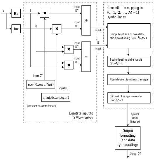
This figure shows the hard-decision M-PSK demodulation floating-point signal diagram for the nontrivial phase offset configuration.
For M > 8, to improve speed and implementation costs, no derotation arithmetic is performed for trivial case (specifically, when phase offset is 0, π/2, π, or 3π/2).
Also, for M > 8, only double and
single input types are supported.
References
[1] Proakis, John G. Digital Communications. 4th ed. New York: McGraw Hill, 2001.
Extended Capabilities
Version History
Introduced before R2006a