Find Delay
Find delay between two signals
Libraries:
Communications Toolbox /
Utility Blocks
Description
The Find Delay block finds the delay between a signal and a delayed, and possibly distorted, version of itself. This is useful when you want to compare a transmitted and received signal to find the bit error rate, but do not know the delay in the received signal. This block accepts a column vector or matrix input signal. For a matrix input, the block outputs a row vector, and finds the delay in each channel of the matrix independently. For more information about signal delays, see Delays in Communication Systems.
This icon shows the block with the optional chg port. ![]()
Examples
Use the Find Delay block to find the delay between two signals. The Find Delay block has a Correlation window length parameter that must be adjusted based on the delay between to the signals. When the correlation window length is too short, the computed delay will not be correct.
Examine Model
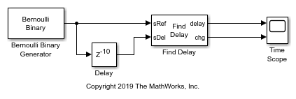
The Bernoulli Binary Generator block is configured to output one sample per second. The output branches to an upper and lower path. The upper path provides a reference signal to the Find Delay block. The lower path provides a delay path to the Find Delay block. A Delay (Simulink) block inserts a delay of 10 samples in the lower path. The Find Delay block compares the two input signals and outputs the calculated delay and the delay change flag. The chg port outputs 0 when the value of the computed delay stays constant for longer than the correlation window length. The chg port outputs 1 to indicate a delay change in the previous correlation window. A time scope displays the delay and the chg outputs of the Find Delay block.
Run Model
Run the model with the Correlation window length parameter set to 15 samples. Observe the chg port output variation over time. Because there is no prior correlation period data for comparison, ignore the Find Delay block outputs for the first correlation window period (time 0 to 15 s).
After the first correlation window period, the calculated delay output shows delay variation over time. For all but one of the correlation windows, the chg port outputs 1 indicating a delay change in the previous correlation window. This result indicates that the correlation window length is too short for the Find Delay block to accurately compute the delay between the two signals.

Run the model with the Correlation window length parameter of the Find Delay block set to 40 samples.
For this run, the calculated delay settles at 10 samples at the 40 second mark, and the chg port toggles to 1 for just one of the correlation window length periods. After the second correlation window period (at the 80 second mark), the computed delay output is stabilized and the chg output toggles to 0 for the remainder of the run.

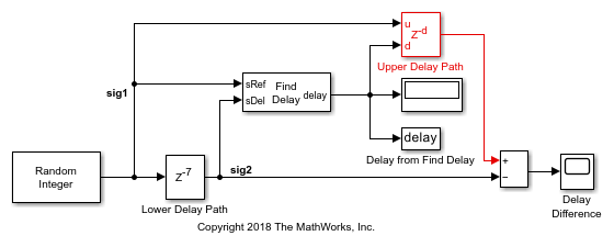
The example computes the delay between a random signal, sig1 and a delayed copy of the signal, sig2, by using the Find Delay block. Signals are delayed and aligned by using instances of the Delay (Simulink) block.
Model Structure
The model uses parallel signal paths to compute and compare the number of samples of delay between signal sig1 and signal sig2.
The upper path uses the
Find Delayblock to compute the delay betweensig1andsig2. TheDelayblock in the upper path inputs the computed signal delay and adds the delay to the reference signalsig1.The lower path adds a fixed delay to the reference signal using the
Delayblock.The signal with the fixed delay and the signal with the computed delay are compared to show the same delay was applied to both signals.
Delayed Signal Comparison
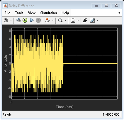
Plot the difference between signals output by the lower delay path and the upper delay path. The plotted delay difference is zero, indicating same delay was applied to both signals. The computed delay is displayed after the simulation runs.
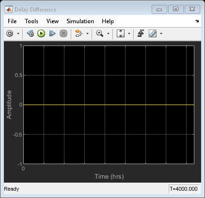
The delay computed by the |Find Delay| block is 7.
For two signals with different sizes and rates, the delay is resolvable as long as the total delay is less than the reference signal frame length. The Find Delay block computes the delay between the multirate signals. The signals are delayed and aligned by using Delay blocks. The buffer output size is adjusted to show resolvable and unresolvable delays.
Model Structure
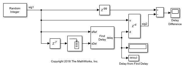
The model uses parallel signal paths to compute and compare the number of samples of delay between two signals, sig1 and sig2.
In the upper path a fixed delay of 99 samples, which equals 7 plus the buffer value, is added to the reference signal.
In the lower path, the Find Delay block computes the delay between the two signals. That amount of delay is applied to the undelayed signal,
sig1, using the Delay (Simulink) block.
Random integer data provides a data stream of 100 sample frames that serves as a reference signal, sig1, and as a delay signal, sig2. The delay between the reference signal and the delay signal is resolvable as long as the buffered signal length plus the discrete delay length are not greater than the frame length of the reference signal.
When the model runs the delay computed by the Find Delay block is displayed. The difference between the reference signal with a fixed delay added and the computed delay added is plotted. When the plotted delay difference is zero, the Find Delay block matches the fixed delay of the input signal.
Delayed Signal Comparison with the Output Buffer Size Set to 92.
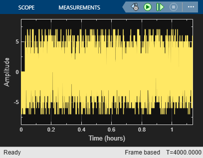
Plot the difference between the fixed delay signal and the output from the Delay block. The plotted delay difference settles to zero, indicating same delay was applied to both signals.
With the buffer set to 92 and a 7 sample delay added to the buffered signal, the total signal delay is 99 samples. The delay is resolvable because the total delay is less than the reference signal frame length of 100 samples.
The total delay computed by the |Find Delay| block is 99.
Delayed Signal Comparison with the Output Buffer Size Set to 94.
Plot the difference between the fixed delay signal and the output from the Delay block. The plotted delay difference remains nonzero for the full simulation, indicating an unresolvable delay difference between the two signals.
With the buffer set to 94 and a 7 sample delay added to the buffered signal, the total signal delay is 101 samples. The delay is unresolvable because the total delay exceeds the reference signal frame length of 100 samples.
The total delay computed by the |Find Delay| block is 101.
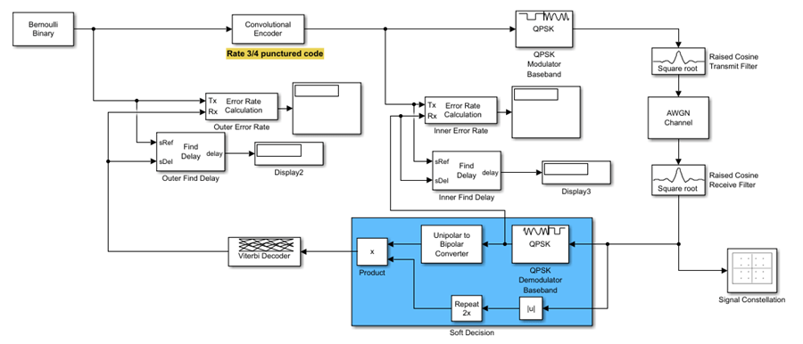
This example shows how to use the Find Delay block to determine the delay between two signals. Here, you can use the same punctured coding model as in Calculate and Specify Receive Delay for Error Rate Block example.
Create and Add Delay Blocks
In the punctured coding model, add two Find Delay blocks: one to determine the receive delay for the Inner Error Rate block and one to determine the receive delay for the Outer Error Rate block.
Simulate Model
Now run the model to view the inner and outer receive delay.
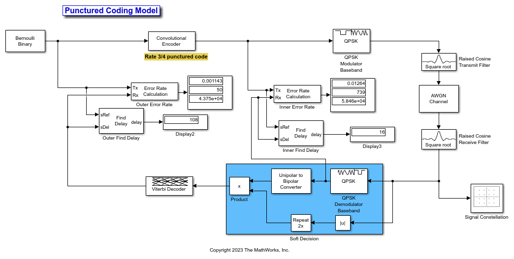
Simulate the model. You can see that the Find Delay block displays have the same values as the receive delay that you calculated in Calculate and Specify Receive Delay for Error Rate Block.
Ports
Input
Output
Parameters
Block Characteristics
More About
Tips
Set the Correlation window length (samples) parameter value sufficiently large so that the computed delay eventually stabilizes at a constant value. When this occurs, the signal from the optional chg output port stabilizes at the constant value of zero.
If the computed delay is not constant, you should increase correlation window length value.
If the increased value of correlation window length exceeds the duration of the simulation, then you should also increase the duration of the simulation accordingly.
If you can roughly estimate the delay, then the correlation window length will produce a stable delay estimate at four times that value.
If the cross-correlation between the two signals is broad, then the Correlation window length (samples) parameter value should be much larger than the expected delay, or else the algorithm might stabilize at an incorrect value. For example, a CPM signal has a broad autocorrelation, so it has a broad cross-correlation with a delayed version of itself. In this case, the Correlation window length (samples) value should be much larger than the expected delay.
If the block calculates a delay that is greater than 75 percent of the Correlation window length (samples) parameter value, the sRef signal is probably delayed relative to the sDel signal. In this case, you should switch the signal lines leading into the two input ports.
To configure the block stop updating the delay after it computes the same delay value for a specified number of samples, select Disable recurring updates, and enter a positive integer in the Number of constant delay outputs to disable updates field. For example, if you set Number of constant delay outputs to disable updates to
20, the block will stop recalculating and updating the delay after it calculates the same value20times in succession. Disabling recurring updates causes the simulation to run faster after the target number of constant delays occurs.
Algorithms
The Find Delay block finds the delay by calculating the cross-correlations of the first signal with time-shifted versions of the second signal, and then finding the index at which the cross-correlation is maximized.
Extended Capabilities
Version History
Introduced before R2006a