Calculate and Specify Receive Delay for Error Rate Block
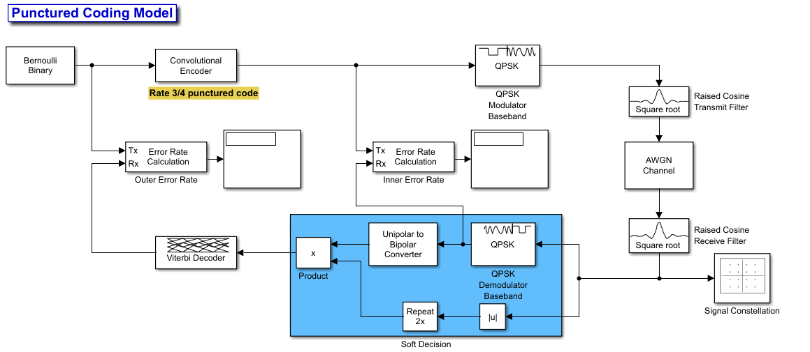
This example shows different processing delays in a punctured coding model and how to calculate the receive delay for the error rate blocks. The example includes delays from decoding, downsampling, and filtering.
Introduction
A receive delay is the total number of sample periods by which the received signal lags behind the transmitted signal. The delay results from processing delay in components, such as transmit and receive filters, modulators, demodulators, encoders, and decoders. These delays are inherent to the algorithms and implementation of these components.
Punctured convolutional coding is a technique that creates a higher-rate code from a lower-rate convolutional code. Puncturing selectively removes some of the encoded bits according to a predefined pattern and adjusts the code rate to meet different system requirements without redesigning the entire encoder and decoder. You can use this error-correcting code to improve the reliability of data transmission over noisy channels.
Create Model
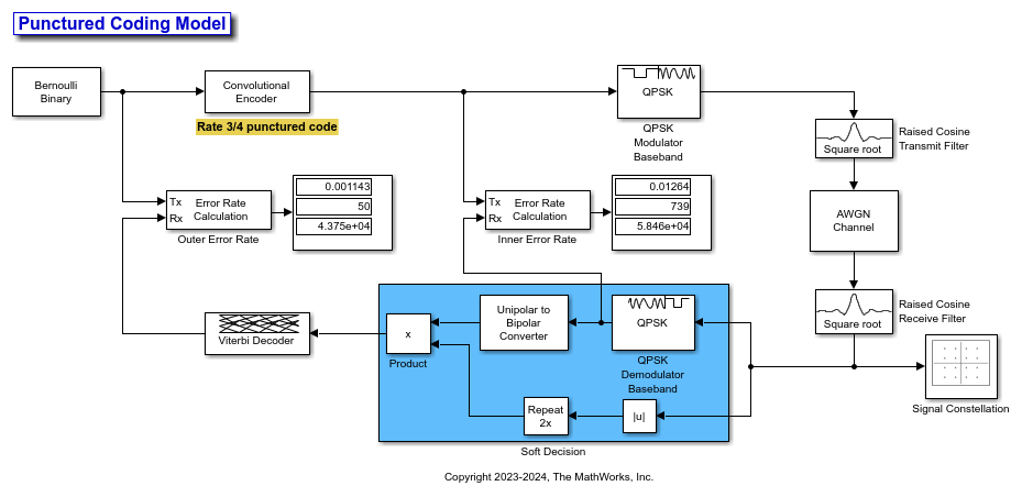
The Simulink® model PuncturedCodingModel includes:
Bernoulli Binary Generator: Produces binary data with equal probability.
Convolutional Encoder with Puncture Pattern: Encodes data, removes bits per pattern (e.g., [1 1 0 1 1 0]) to increase code rate.
QPSK Modulator Baseband: Modulates the punctured bitstream for transmission.
AWGN Channel: Adds noise to the signal.
Raised Cosine Transmit Filter and Raised Cosine Receive Filter Filter: Limit bandwidth and reduce intersymbol interference (ISI).
QPSK Demodulator Baseband: Converts signal back to bitstream with errors.
Viterbi Decoder: Decodes bitstream, estimates missing bits and corrects errors.
Error Rate Calculation Blocks: Measure BER before and after decoding to assess system performance. The error rate blocks need to have accurate receive delay inputs from the model to give the correct performance results.

Set Receive Delay for Inner Error Rate Block
The delays that affect the Inner Error Rate block come from two other blocks: the TX Filter and the RX Filter.
The TX filter increases the rate of the input signal by a factor of 8 and filters it with a raised cosine filter. It has a filter span of 6 symbols, which results in a group delay of 3 symbols. At the start of the simulation, this block outputs an initial frame of zeros. The input frame size is 2, so the total delay introduced by this block is 2 (initial frame size) + 3 (group delay) = 5 symbols. Since the delay is measured at the input rate, these 5 symbols translate directly to 5 samples.
The RX filter decimates the input signal by a factor of 8 and applies a raised cosine filter. It also has a filter span of 6 symbols, leading to a group delay of 3 symbols. The 3 symbols of delay at the output correspond to 3 samples because decimation does not change the number of delay symbols.
The sum of delays from the TX filter and RX filter is 5 + 3 = 8 symbols.
The QPSK Demodulator block takes complex QPSK signals and outputs 2 bits for each input symbol. When converting to output bits, it effectively doubles the cumulative delay at its input. Multiply the TX + RX delay of 8 symbols by 2. The total delay is 16. No other blocks are causing delays between the two input signals of the Inner Error Rate block.
Set the Receive delay parameter in the Inner Error Rate block to 16.
Set Receive Delay for Outer Error Rate
The Outer Error Rate block calculates the bit error rate for the entire model, including the part that uses punctured convolutional coding. This block looks at the entire system to see how many bits were sent incorrectly. The Outer Error Rate block delay comes from three main sources: the TX Filter block, the RX Filter block, and the Viterbi Decoder block.
The TX Filter block and the RX Filter block have a combined delay of 16 samples.
The Viterbi Decoder block decodes encoded data by using a punctured convolutional code, which has a rate of 3/4. The decoding process shortens the delay present at its input by a factor of 3/4, resulting in a reduced delay of 12 samples (16 multiplied by 3/4). The Viterbi Decoder block also has a delay because of a traceback path it uses to decode the data. This process adds a delay equal to the Traceback depth parameter, which is 96 samples.
The total delay is the 12 samples reduced delay from the Viterbi Decoder block plus the 96 samples delay from its traceback process, giving a delay 108 samples.
Set the Receive delay parameter in the Outer Error Rate block to 108.
Simulate Model
Now run the model to see the effect of your receive delay parameter settings.


The constellation diagram shows the transmitted symbols as points on the QPSK constellation. The actual positions of the points are perturbed slightly due to noise. As expected, you see clusters of points around the four ideal QPSK constellation positions.