BPSK Demodulator Baseband
Demodulate BPSK-modulated data
Libraries:
Communications Toolbox /
Modulation /
Digital Baseband Modulation /
PSK
Communications Toolbox HDL Support /
Modulation /
PM
Description
The BPSK Demodulator Baseband block demodulates a signal that was modulated using the binary phase shift
keying (BPSK) method. The input is a baseband representation of the modulated signal.
This block accepts a scalar or column vector input signal. The input signal must be a
discrete-time complex signal. The block maps the points exp(jϕ) or -exp(jϕ) to 0 and 1, respectively. The Phase offset
(rad) parameter specifies the value of ϕ.
Examples
Use a CRC code to detect frame errors in a noisy BPSK signal.
In the cm_ex_crc_noisy_bpsk_frames model, the CRC generator and detector pair use a standard CRC-4 polynomial,  . The length of the CRC is 4 bits as determined by the degree of the polynomial. The number of checksums per frame is 1, so the full transmission frame has one CRC appended at the end.
A binary signal frame gets a CRC code appended to the end of the frame. BPSK modulation is applied to the signal and the signal passes through an AWGN channel. The signal is demodulated, and then a CRC syndrome detector removes the CRC and calculates the CRC errors.

Generate 12-bit frames of binary data and append CRC bits. Based on the degree of the polynomial, 4 bits are appended to each frame. Apply BPSK modulation and pass the signal through an AWGN channel. Demodulate and use the CRC detector to determine if the frame is in error.

The results of the CRC detection are compared to a BER calculation.
Number of bit errors detected:  6
Number of crc errors detected:  7
Extended Examples
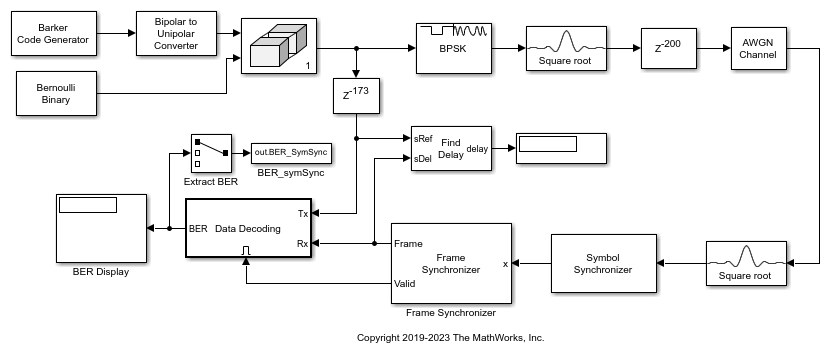
Frame Synchronization Using Barker Code Preamble
Use a length 13 Barker code frame preamble for frame synchronization of data bits.
Ports
Input
BPSK-modulated baseband signal, specified as a scalar, vector, or
matrix. When this input is a matrix, each column is treated as an
independent channel. This port is unnamed until the
Var port is enabled. When the noise variance or
signal power result in computations involving extreme positive or
negative magnitudes, see BPSK Soft Demodulation for
demodulation decision type considerations.
Data Types: double | single | fixed point
Complex Number Support: Yes
Noise variance, specified as a positive scalar or vector of positive values. When the noise variance or signal power result in computations involving extreme positive or negative magnitudes, see BPSK Soft Demodulation for demodulation decision type considerations.
Dependencies
To enable this parameter, set the Noise variance
source parameter to
Port.
Data Types: double
Output
Demodulated signal, returned as a scalar or vector. If the output is a scalar, the value is an integer. If the output is a vector, it is an integer-valued or binary-valued vector.
Data Types: single | double | int8 | int16 | int32 | uint8 | uint16 | uint32 | Boolean
Parameters
To edit block parameters interactively, use the Property Inspector. From the Simulink® Toolstrip, on the Simulation tab, in the Prepare gallery, select Property Inspector.
Main
Decision type used during demodulation, specified as Hard
decision, Log-likelihood
ratio or Approximate log-likelihood
ratio. For more information, see BPSK Hard-Decision Demodulation and BPSK Soft Demodulation.
The output matches the data type of the input values when
Decision type is set to
Log-likelihood
								ratio
or
Approximate log-likelihood
								ratio
.
Noise variance source, specified as Dialog
or Port.
Dialog— The noise variance is set using theNoise varianceparameter.Port— The noise variance is set using theVarinput port.
Noise variance, specified as a positive scalar or vector of positive values.
When specified as a scalar, that value is used on all elements in the input signal.
When specified as a vector, the vector length must be equal to the number of columns in the input signal. Each noise variance vector element is applied to its corresponding column in the input signal.
When the noise variance or signal power result in computations involving extreme positive or negative magnitudes, see BPSK Soft Demodulation for demodulation decision type considerations.
This parameter is tunable in normal mode, accelerator mode and rapid accelerator mode. If you use the Simulink Coder™ rapid simulation (RSIM) target to build an RSIM executable, then you can tune the parameter without recompiling the model. This is useful for Monte Carlo simulations, in which you run the simulation multiple times (perhaps on multiple computers) with different amounts of noise.
Tunable: Yes
Dependencies
To enable this parameter, set the Decision type parameter to set to either
Log-likelihood ratio or
Approximate log-likelihood ratio and
set the Noise variance source parameter to
Dialog.
Phase of the zeroth point, specified as a real-valued scalar. Units are in radians.
Example: pi/4
Data Types
Output data type, specified as one of these options
When you set the Decision type parameter to Hard decision:
Inherit via internal rule— The block inherits the output data type from the input port. If the input is a floating-point type (singleordouble), the output data type is the same as the input data type. If the input data type is fixed-point, the output data type works as if you set this parameter toSmallest unsigned integer.Smallest unsigned integer— The block selects the output data type based on the settings used in the Hardware Implementation pane of the Configuration Parameters dialog box of the model. If you selectASIC/FPGAin the Hardware Implementation pane, the output data type is the ideal minimum one-bit size, that is,ufix(1). For all other selections, the output data type is an unsigned integer with the smallest available word length large enough to fit one bit, usually corresponding to the size of a character (for example,uint8).doublesingleint8uint8int16uint16int32uint32boolean
When you set the Decision type parameter to Log-likelihood ratio or Approximate log-likelihood ratio — The block inherits the output data type matches the data type of the input.
For information about specifying data types, see Data Type Assistant.
Derotate factor, specified as Same word length as
input or Specify word
length.
Dependencies
This parameter applies only when the input is fixed-point and the Phase offset (rad) parameter is not a multiple of π/2.
Block Characteristics
More About
The Data Type Assistant helps you set data
attributes. To use the Data Type Assistant, click ![]() . For more information, see Specify Data Types Using Data Type Assistant (Simulink).
. For more information, see Specify Data Types Using Data Type Assistant (Simulink).
Algorithms
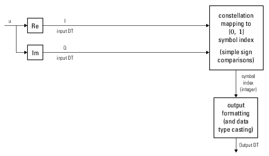
When applying hard demodulation, the input signal type and phase offset are considered.
This figure shows the hard decision BPSK demodulator for a floating-point or fixed-point signal and trivial phase offset (multiple of π/2)

This figure shows the hard decision BPSK demodulator for a floating-point signal and nontrivial phase offset

This figure shows the hard decision BPSK demodulator for a fixed-point signal and nontrivial phase offset

For soft demodulation, two soft-decision log-likelihood ratio (LLR) algorithms are available: exact LLR and approximate LLR. The exact LLR algorithm is more accurate but has slower execution speed than the approximate LLR algorithm. For further description of these algorithms, see the Hard- vs. Soft-Decision Demodulation topic.
Note
The exact LLR algorithm computes exponentials using finite precision arithmetic. For computations involving very large positive or negative magnitudes, the exact LLR algorithm yields:
Infor-Infif the noise variance is a very large valueNaNif the noise variance and signal power are both very small values
The approximate LLR algorithm does not compute exponentials. You can avoid
Inf, -Inf, and NaN results by using
the approximate LLR algorithm.
Extended Capabilities
C/C++ Code Generation
Generate C and C++ code using Simulink® Coder™.
HDL Coder™ provides additional configuration options that affect HDL implementation and synthesized logic.
This block has one default HDL architecture.
| ConstrainedOutputPipeline | Number of registers to place at
the outputs by moving existing delays within your design. Distributed
pipelining does not redistribute these registers. The default is
|
| InputPipeline | Number of input pipeline stages
to insert in the generated code. Distributed pipelining and constrained
output pipelining can move these registers. The default is
|
| OutputPipeline | Number of output pipeline stages
to insert in the generated code. Distributed pipelining and constrained
output pipelining can move these registers. The default is
|
Version History
Introduced before R2006a
MATLAB Command
You clicked a link that corresponds to this MATLAB command:
Run the command by entering it in the MATLAB Command Window. Web browsers do not support MATLAB commands.
Website auswählen
Wählen Sie eine Website aus, um übersetzte Inhalte (sofern verfügbar) sowie lokale Veranstaltungen und Angebote anzuzeigen. Auf der Grundlage Ihres Standorts empfehlen wir Ihnen die folgende Auswahl: .
Sie können auch eine Website aus der folgenden Liste auswählen:
So erhalten Sie die bestmögliche Leistung auf der Website
Wählen Sie für die bestmögliche Website-Leistung die Website für China (auf Chinesisch oder Englisch). Andere landesspezifische Websites von MathWorks sind für Besuche von Ihrem Standort aus nicht optimiert.
Amerika
- América Latina (Español)
- Canada (English)
- United States (English)
Europa
- Belgium (English)
- Denmark (English)
- Deutschland (Deutsch)
- España (Español)
- Finland (English)
- France (Français)
- Ireland (English)
- Italia (Italiano)
- Luxembourg (English)
- Netherlands (English)
- Norway (English)
- Österreich (Deutsch)
- Portugal (English)
- Sweden (English)
- Switzerland
- United Kingdom (English)
