LTE OFDM Demodulation of Streaming Samples
This example shows how to use the LTE OFDM Demodulator block to return the LTE resource grid from streaming samples. You can generate HDL code from this block.
Generate input LTE OFDM symbols using LTE Toolbox™. Select a reference channel based on NDLRB, and specify the type of cyclic prefix.
enb = lteRMCDL('R.5');
enb.TotSubframes = 1;
enb.CyclicPrefix = 'Normal';  % or 'Extended'
% ------------------------------------------------------------
%      NDLRB  |   Reference Channel
% ------------------------------------------------------------
%   6         |   R.4
%   15        |   R.5
%   25        |   R.6
%   50        |   R.7
%   75        |   R.8
%   100       |   R.9
% ------------------------------------------------------------

[waveform,LTEGrid,info] = lteRMCDLTool(enb,[1;0;0;1]);
%%In this example, the Input data sample rate parameter is set to |Use
% maximum input data sample rate|. Hence, the LTE OFDM Demodulator block
% expects input samples at 30.72 MHz sample rate to correspond to the
% size of the FFT. The sample rate of |waveform| depends on NDLRB,
% so the generated waveform might be at a lower rate. To generate
% a test waveform, upsample the signal to 30.72 MHz, normalize the power,
% and add noise. Scale the signal magnitude to be in the range -1 to 1 for
% easy conversion to fixed-point types.

FsRx = 30.72e6;
FsTx = info.SamplingRate;
% --------------------------------------------------------------
%      NDLRB              |   Sampling Rate (MHz)
%   ------------------------------------------------------------
%   1) 6                  |   1.92
%   2) 15                 |   3.84
%   3) 25                 |   7.68
%   4) 50                 |   15.36
%   5) 75                 |   30.72
%   6) 100                |   30.72
%   ------------------------------------------------------------

tx = resample(waveform,FsRx,FsTx);
avgTxPower =  (tx' * tx) / length(tx);
tx = tx / sqrt(avgTxPower);
n = 0.1 * complex(randn(length(tx),1),randn(length(tx),1));
rx = tx + n;
rx = 0.99 * rx / max(abs(rx));
Use an LTE Toolbox function as a behavioral reference for the OFDM demodulation. Downsample the test waveform to the actual sample rate for the selected NDLRB. Then, compensate for the scale factor that results from the difference in FFT sizes.
refInput = resample(rx,FsTx,FsRx);
refGrid = lteOFDMDemodulate(info,refInput);
refGrid = refGrid * FsRx/FsTx;
Set up the Simulink™ model input data. Convert the test waveform to a fixed-point data type to model the result from a 12-bit ADC. The Simulink sample time is 30.72 MHz.
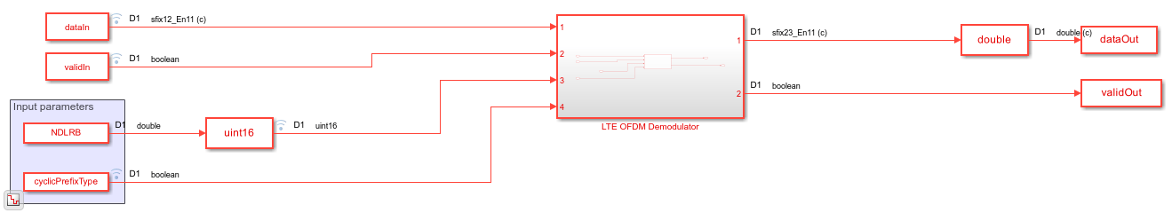
The Simulink model imports the sample stream dataIn and validIn, the input parameters NDLRB and cyclicPrefixType, and the variable stopTime.
NDLRB = info.NDLRB;
if strcmp(info.CyclicPrefix,'Normal')
    cyclicPrefixType = false;
else
    cyclicPrefixType = true;
end

sampling_time = 1/FsRx;
dataIn = fi(rx,1,12,11);
validIn = true(length(dataIn),1);
Calculate the Simulink simulation time, accounting for the latency of the LTE OFDM Demodulator block. The latency of the FFT is fixed because the block uses a 2048-point FFT. Assume the maximum possible latency of the cyclic prefix removal and subcarrier selection operations. The simulation must run long enough to apply the input data, plus the latency of the final input symbol.
FFTlatency = 4137;
CPRemove_max = 512; % extended CP
carrierSelect_max = 424; % NDRLB 100
stopTime = sampling_time*(length(dataIn)+CPRemove_max+FFTlatency+carrierSelect_max);
Run the Simulink model. The model imports the dataIn and validIn structures and returns dataOut and validOut.
modelname = 'LTEOFDMDemodulatorExample';
open(modelname)
set_param(modelname,'SampleTimeColors','on');
set_param(modelname,'SimulationCommand','Update');
sim(modelname)
ans =

  logical

   1
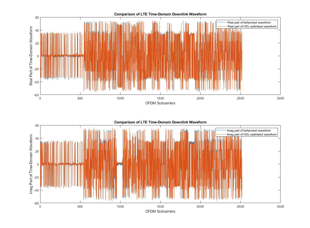
Compare the output of the Simulink model against the behavioral results, and calculate the SQNR of the HDL-optimized LTE OFDM Demodulator block.
rxgridSimulink = dataOut(validOut);

figure('units','normalized','outerposition',[0 0 1 1])
subplot(2,1,1)
plot(real(refGrid(:)))
hold on
plot(squeeze(real(rxgridSimulink)))
legend('Real part of behavioral waveform','Real part of HDL-optimized waveform')
title('Comparison of LTE Time-Domain Downlink Waveform')
xlabel('OFDM Subcarriers')
ylabel('Real Part of Time-Domain Waveform')

subplot(2,1,2)
plot(imag(refGrid(:)))
hold on
plot(squeeze(imag(rxgridSimulink)))
legend('Imag part of behavioral waveform','Imag part of HDL-optimized waveform')
title('Comparison of LTE Time-Domain Downlink Waveform')
xlabel('OFDM Subcarriers')
ylabel('Imag Part of Time-Domain Waveform')

sqnrRealdB = 10*log10(var(real(rxgridSimulink))/abs(var(real(rxgridSimulink))-var(real(refGrid(:)))));
sqnrImagdB = 10*log10(var(imag(rxgridSimulink))/abs(var(imag(rxgridSimulink))-var(imag(refGrid(:)))));

fprintf('\n LTE OFDM Demodulator: \n SQNR of real part is %.2f dB',sqnrRealdB)
fprintf('\n SQNR of imaginary part is %.2f dB\n',sqnrImagdB)
 LTE OFDM Demodulator:
 SQNR of real part is 25.98 dB
 SQNR of imaginary part is 23.23 dB