Runtime Image Resizing
This example shows how to configure and use the Image Resizer block with variable input and output image sizes.
Runtime Programmable Image Resizer
The Image Resizer block is capable of operating on images that vary in size without recompilation. It also supports variable output sizes for each image.
Runtime programmable resizing lets you use a single FPGA bitstream for a wide range of data and configurations with minimal additional resource costs. A programmable architecture can be used for applications such as preprocessing data for a deep learning network as in the Deploy and Verify YOLO v2 Vehicle Detector on FPGA example.
To configure the Image Resizer block to be runtime programmable, select Input port for the Input size source and/or Output size source. This setting allows you to specify the size of each frame at runtime by using the respective input ports.
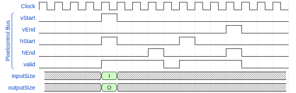
The inputSize and outputSize input ports are sampled on each vStart of the pixelcontrol bus. The input values must not exceed the Maximum input size and Maximum output size parameters respectively. If the input values exceed the maximums, the Image Resizer block uses the closest valid values.
When configuring your pixel stream, a single sample rate must be maintained. If you are using multiple Frame To Pixels blocks in Simulink® then you must ensure that Total pixels per line and Total video lines are constant across all Frame To Pixels blocks in the model.
Example Model
The example model takes inputs from the MATLAB workspace with the From Workspace blocks, and uses these to drive the Image Resizer block. The output is captured using To Workspace blocks and the pixelcontrol bus timings displayed using a Measure Timing block.

The output of the From Workspace blocks for the pixelcontrol bus, inputSize, and outputSize are in 1D interpreted timeseries format. The Pixel Control Bus Creator block and the reshape blocks convert the inputs to the expected pixelcontrol bus and 1-by-2 row vectors.
To easily view the variable sized output of a runtime programmable Image Resizer block, you can convert the pixel stream output to a frame by using a Pixels To Frame block that is configured for a frame size that is greater than or equal to the Image Resizer block's Maximum output size. The Pixels To Frame zero-pads any extra values when it receives a vEnd for a frame smaller than its configured frame size.
The Measure Timing block provides each output frame's width and height from the activePixels and activeLines ports. The measurements related to blanking; totalPixels, totalLines, horizBlank, verBlank are determined over more than one frame so are inaccurate for a variable output size.
Model Test Bench
The RuntimeProgrammableImageResizeTestBench.m script generates the inputs for the Image Resizer block, opens the RuntimeProgrammableImageResize.slx model, simulates the model, and displays the output frames.
This example shows a MATLAB® test bench rather than verifying the results in Simulink as it simplifies the conversions between frames and pixel streams which would require multi-rate sample times for the frame-based and pixel-based blocks in Simulink.
The VideoObj object reads each frame from a video source which is converted from RGB to grayscale. The test bench uses the imresize function to convert each frame to match the desired InputSize. Next the frm2pix object converts the frame to a stream of pixels and control structures. The video source and each frame's input and output size are specified in the TB struct:
TB.VideoFileName = 'rhinos.avi';
TB.InputSize  = {[240, 320], [120, 160], [200, 200], [128, 128], [192, 108], [240, 320]};
TB.OutputSize = {[120, 120], [120, 120], [120, 120], [ 54,  96], [ 64,  64], [108, 192]};
These settings show resizing 3 frames of varying input size to a single output size and then resizing 3 frames that vary both input and output size.
Once all the input frames have been converted to a pixel stream, the input and output size for each frame is used to generate a vector of values that will drive the respective inputSize and outputSize ports. Here each input and output size value is repeated until the next vStart where the next frame's values will replace it.
Once all the stimuli have been created the vectors are converted to timeseries objects for use with the From Workspace blocks.
The script runs the simulation and captures the output pixel stream. The outputs are then converted back to frames using the pix2frm object. The test bench script creates a montage of input and output frames. The input and output frames are both zero padded to the test bench's MaxFrameSize for display. The viewMontage function accepts the TB struct and a frame rate as inputs and displays the input/output visualization.
Generate HDL Code and Verify Its Behavior
To check and generate the HDL code referenced in this example, you must have an HDL Coder™ license.
To generate the HDL code, use the following command:
makehdl('RuntimeProgrammableImageResize/DUT');
To generate a test bench, use the following command:
makehdltb('RuntimeProgrammableImageResize/DUT');
The design was synthesized and put through place and route on an AMD™ Zynq™ ZC706 board. A clock rate of 270 MHz was achieved with the following resource usage:
              Resources
              _________

    LUT         1537
    LUTRAM        47
    FF          2737
    BRAM           4
    DSP           12