Image Filter
2-D FIR filtering
Libraries:
Vision HDL Toolbox /
Filtering
Description
The Image Filter block performs two-dimensional finite impulse response (FIR) filtering on a pixel stream and supports the use of programmable filter coefficients.
Examples

Design Video Processing Algorithms for HDL in Simulink
Design a hardware-targeted image filter using Vision HDL Toolbox™ blocks.
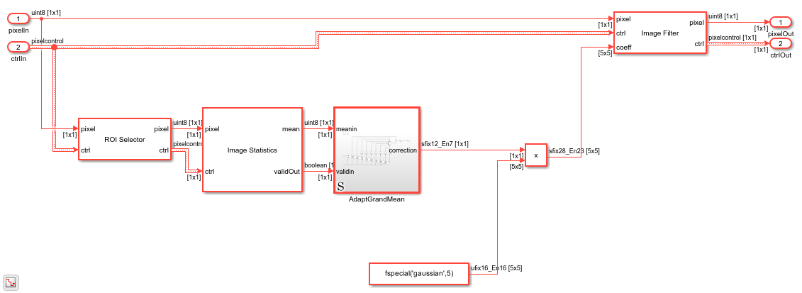
Adapt Image Filter Coefficients from Frame to Frame
Use programmable coefficients to correct a time-varying impairment on the input video.
Filter Multipixel Video Streams
Design filters that operate on a multipixel input video stream. Use multipixel streaming to process high-resolution or high-frame-rate video with the same synthesized clock frequency as a single-pixel streaming interface. Multipixel streaming also improves simulation speed and throughput because fewer iterations are required to process each frame, while maintaining the hardware benefits of a streaming interface.
Ports
This block uses a streaming pixel interface with a bus for
frame control signals. This interface enables the block to operate independently of image size
and format. The pixel ports on this block support single pixel streaming or
multipixel streaming. Single pixel streaming accepts and returns a single pixel value each clock
cycle. Multipixel streaming accepts and returns a vector of M pixels per
clock cycle to support high-frame-rate or high-resolution formats. The M
value corresponds to the Number of pixels parameter of the Frame
To Pixels block. Along with the pixel, the block accepts and returns a
pixelcontrol bus that contains five control signals. The control signals
indicate the validity of each pixel and their location in the frame. For multipixel streaming,
one set of control signals applies to all pixels in the vector. To convert a frame (pixel
matrix) into a serial pixel stream and control signals, use the Frame
To Pixels block. For a full description of the interface, see Streaming Pixel Interface.
Input
Output
Parameters
Tips
When you use a block with an internal line buffer inside an Enabled Subsystem (Simulink), the enable signal pattern must maintain the timing of the pixel stream, including the minimum blanking intervals. If the enable pattern corrupts the timing of the pixel stream, you might see partial output frames, corrupted pixel stream control signals, or mismatches between Simulink® and HDL simulation results. You may need to extend the blanking intervals to accommodate for cycles when the enable is low. For more information, see Configure Blanking Intervals.
Algorithms
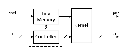
The block implements the 2-D FIR filter with a fully pipelined architecture. Each multiplier has two pipeline stages on each input and two pipeline stages on each output. The adder is a pipelined tree structure. HDL code generation uses symmetric, unity, or zero-value coefficients to reduce the number of multipliers.
When you use multipixel streaming, the block uses a single line memory and implements one filter kernel for each of the M input pixels, in parallel. This increase in hardware resources is a trade off for increasing throughput compared to single-pixel streaming.
When you provide coefficients using the Filter coefficients
parameter, you can optimize the multipliers for HDL code generation by using a canonical
signed digit (CSD) representation or factored CSD representation. To use a CSD of factored CSD
representation, right-click the block, and in the HDL Coder app section,
click the HDL Block Properties option. Then, set the
ConstMultiplierOptimization parameter to csd
or fcsd.
When you provide coefficients using the coeff port, the latency depends on the size of the filter coefficients. For an N-by-M coefficient matrix provided using the coeff port, the block generates NxM multipliers.
The latency of the block is the line buffer latency plus the
latency of the kernel calculation. The line buffer latency includes edge padding by default. The
latency of the padding operation depends on the size of the kernel. If edge padding is not
necessary for your design, you can reduce the latency by setting the Padding
method parameter to None. When you use this option, the block
latency does not depend on your kernel size. To determine the exact latency for any
configuration of the block, measure the number of time steps between the input and output
control signals.
The block shows its latency on the block mask. The latency displays as a number of lines
and pixels. The exact number of clock cycles depends on the number of pixels in a line of
your image frame and the input pixel valid pattern. Use the displayed latency information
along with the pixelcontrol bus signals to align parallel data paths in
your design.
Note
When you use edge padding, use a horizontal blanking interval of at least twice the kernel width. This interval lets the algorithm finish processing one line before it starts processing the next one, including adding padding pixels before and after the active pixels in the line.
The horizontal blanking interval is equal to TotalPixelsPerLine – ActivePixelsPerLine or, equivalently, FrontPorch + BackPorch. Standard streaming video formats use a horizontal blanking interval of about 25% of the frame width. This interval is much larger than the filters applied to each frame.
The horizontal blanking interval must also meet these minimums:
If the kernel size is less than 4, and you use edge padding, the total porch must be at least 8 pixels.
When you disable edge padding, the horizontal blanking interval must be at least 12 cycles and is independent of the kernel size.
The BackPorch must be at least 6 pixels. This parameter is the number of inactive pixels before the first valid pixel in a frame.
For more information, see Configure Blanking Intervals.
Extended Capabilities
Version History
Introduced in R2015aSee Also
2-D FIR
Filter (Computer Vision Toolbox) | Frame To Pixels | visionhdl.ImageFilter