Independent Suspension - K and C
Libraries:
Vehicle Dynamics Blockset /
Suspension
Description
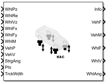
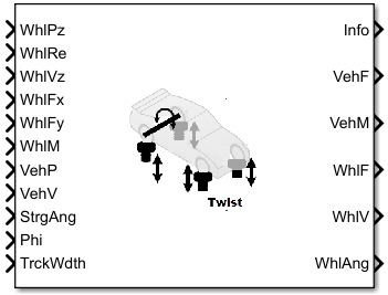
In the Vehicle Dynamics Blockset™ library, there are two types of suspension blocks that implement the kinematics and compliance (K and C) test suspension characteristics measured from simulated or actual laboratory suspension tests.
| Block | Suspension type Setting | Implementation |
|---|---|---|
Twist-Beam Suspension - K and C
|
| Kinematics and compliance effects of:
For more information, see Twist-Beam Suspension - K and C. |
Independent Suspension - K and C
|
| Kinematics and compliance effects of four independent suspensions on a vehicle with two axles and two wheels per axle. |
K and C Effects on Suspension
To determine the overall suspension forces and geometric effects on the vehicle and wheels, the block adds the individual effects from kinematic (bounce, roll, steering) and compliance (longitudinal and lateral forces, aligning moments) inputs. Specifically, the block multiplies the suspension geometry states by either gradient or table values to determine the K and C effects on wheel orientation and suspension forces.
Wheel orientation:
Camber, caster, and steer angles
Lateral wheel center displacement
Longitudinal wheel center displacement
Vertical suspension forces:
Anti-sway bar
Shock force
Wheel rate
Contact patch swing arm (CPSA) force
Longitudinal side view swing arm (SVSA) anti-effects
The block uses these parameters to account for the K and C effects on the camber, caster, and steer angles.
Bounce test– Independent suspension
Roll test– Independent suspension
Steer test
Longitudinal compliance test
Lateral compliance-opposed test
Aligning torque compliance-opposed test
Use the Static alignment settings parameters to set the initial state of the suspension.
The block uses these parameters to account for the K and C effects the lateral wheel center displacement.
Bounce test
Longitudinal compliance test
Lateral compliance-opposed test
The block uses these parameters to account for the K and C effects on the longitudinal wheel center displacement.
Bounce test
Longitudinal compliance test
The block uses the Shock force parameters to calculate the shock force effect on the vertical suspension force. You can specify table-based or constant parameter values.
The block uses the Bounce test parameters to calculate the wheel rate effect on the vertical suspension force.
The block uses these equations to calculate the effect of the contact patch swing arm (CPSA) forces on vertical suspension force.
The block also uses the Static loaded radius of wheels parameter in the CPSA force calculation.
The equations use these variables.
| ϴCPSA | Contact patch swing arm angle |
| Fy | Lateral suspension force |
| FzCPSA | CPSA effect on vertical suspension force |
| zw | Wheel displacement |
The block uses these equations to calculate the effect of the side view swing arm (SVSA) forces on vertical suspension force during acceleration and braking.
Use the Drivetrain type parameter to ensure that the block applies the acceleration anti-effects to the correct wheels.
The equations use these variables.
| ϴSVSA | Contact patch swing arm angle |
| Fx | Longitudinal wheel force |
| FzSVSA | SVSA effect on vertical suspension force |
| zw | Wheel displacement |
Anti-Sway Bar
Optionally, use the Anti-sway axle enable by axle, AntiSwayEnByAxl parameter to implement anti-sway bar reaction forces by axle.
If you enable an anti-sway bar on the axle, the anti-sway bar stiffness is the difference between the anti-sway bar torque parameter, Suspension roll stiffness with anti-roll bar, RollStiffArb, and the roll stiffness parameter measured with no anti-sway bar present Suspension roll stiffness without anti-roll bar, RollStiffNoArb.
If you do not enable an anti-sway bar, the roll stiffness is 0.
Examples
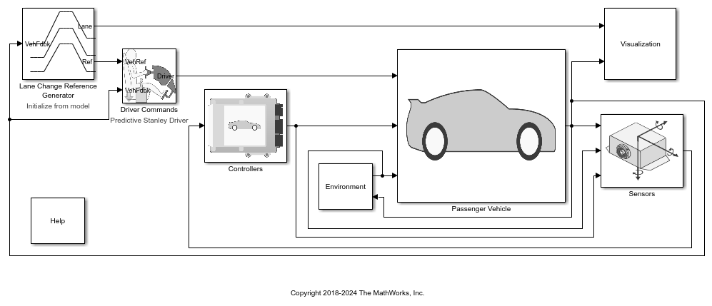
Double Lane Change Reference Application
Simulate a full vehicle dynamics model undergoing a double lane change maneuver standard ISO 3888-2. Use for vehicle dynamics ride and handling analysis and chassis controls development, including yaw stability and lateral acceleration limits.
Ports
The block uses the wheel number, t, to index the input and output signals. This table summarizes the wheel, axle, and corresponding wheel number for a vehicle with:
Two axles
Two wheels per axle
| Wheel | Axle | Wheel Number |
|---|---|---|
| Front left | Front | 1 |
| Front right | Front | 2 |
| Rear left | Rear | 1 |
| Rear right | Rear | 2 |
Input
Wheel displacement, zw, along vehicle-fixed
z-axis, in m. Array dimensions are 1 by the
total number of wheels on the vehicle.
For example, for a two-axle vehicle with two wheels per axle, the
WhlPz:
Signal array dimensions are
[1x4].Wheel Array Element Axle Wheel Number Front left WhlPz(1,1)11Front right WhlPz(1,2)12Rear left WhlPz(1,3)21Rear right WhlPz(1,4)22
Effective wheel radius, Rew, in m. Array
dimensions are 1 by the total number of wheels on the vehicle.
For example, for a two-axle vehicle with two wheels per axle, the
WhlRe:
Signal array dimensions are
[1x4].Wheel Array Element Axle Wheel Number Front left WhlRe(1,1)11Front right WhlRe(1,2)12Rear left WhlRe(1,3)21Rear right WhlRe(1,4)22
Wheel velocity, żw, along wheel-fixed
z-axis, in m. Array dimensions are 1 by the
total number of wheels on the vehicle.
For example, for a two-axle vehicle with two wheels per axle, the
WhlVz:
Signal array dimensions are
[1x4].Wheel Array Element Axle Wheel Number Front left WhlVz(1,1)11Front right WhlVz(1,2)12Rear left WhlVz(1,3)21Rear right WhlVz(1,4)22
Longitudinal wheel force applied to vehicle,
Fwx, along the inertial-fixed
x-axis. Array dimensions are 1 by the total
number of wheels on the vehicle.
For example, for a two-axle vehicle with two wheels per axle, the
WhlFx:
Signal array dimensions are
[1x4].Wheel Array Element Axle Wheel Number Front left WhlFx(1,1)11Front right WhlFx(1,2)12Rear left WhlFx(1,3)21Rear right WhlFx(1,4)22
Lateral wheel force applied to vehicle,
Fwy, along the inertial-fixed
y-axis. Array dimensions are 1 by the total number
of wheels on the vehicle.
For example, for a two-axle vehicle with two wheels per axle, the
WhlFy:
Signal array dimensions are
[1x4].Wheel Array Element Axle Wheel Number Front left WhlFy(1,1)11Front right WhlFy(1,2)12Rear left WhlFy(1.3)21Rear right WhlFy(1,4)22
Longitudinal, lateral, and vertical suspension
moments at axle a, wheel t, applied to the wheel at the
axle wheel carrier reference coordinate, in N·m. Input array dimensions are
3 by the number of wheels on the vehicle.
WhlM(1,...)— Suspension moment applied to the wheel about the inertial-fixed x-axis (longitudinal)WhlM(2,...)— Suspension moment applied to the wheel about the inertial-fixed y-axis (lateral)WhlM(3,...)— Suspension moment applied to the wheel about the inertial-fixed z-axis (vertical)
The wheel moment is positive when the axle rotates counter-clockwise, as defined by the + WhlMz used in compliance tests parameter. By default the block implements the ISO coordinate system. For more information, see Directions.
For example, for a two-axle vehicle with two
wheels per axle, the WhlM:
Signal dimensions are
[3x4].Signal contains suspension moments applied to four wheels according to their axle and wheel locations.
Wheel Array Element Axle Wheel Number Moment Axis Front left WhlM(1,1)11Inertial-fixed x-axis (longitudinal) Front right WhlM(1,2)12Rear left WhlM(1,3)21Rear right WhlM(1,4)22Front left WhlM(2,1)11Inertial-fixed y-axis (lateral) Front right WhlM(2,2)12Rear left WhlM(2,3)21Rear right WhlM(2,4)22Front left WhlM(3,1)11Inertial-fixed z-axis (vertical) Front right WhlM(3,2)12Rear left WhlM(3,3)21Rear right WhlM(3,4)22
Vehicle displacement from axle a, wheel t along
vehicle-fixed coordinate system, in m. Input array dimensions are 3
by the number of wheels on the vehicle.
VehP(1,...)— Vehicle displacement from wheel, xv, along the inertial-fixed x-axisVehP(2,...)— Vehicle displacement from wheel, yv, along the inertial-fixed y-axisVehP(3,...)— Vehicle displacement from wheel, zv, along the inertial-fixed z-axis
For example, for a two-axle vehicle with two wheels per axle, the
VehP:
Signal dimensions are
[3x4].Signal contains four displacements according to their axle and wheel locations.
Wheel Array Element Axle Wheel Number Axis Front left VehP(1,1)11Inertial-fixed x-axis Front right VehP(1,2)12Rear left VehP(1,3)21Rear right VehP(1,4)22Front left VehP(2,1)11Inertial-fixed y-axis Front right VehP(2,2)12Rear left VehP(2,3)21Rear right VehP(2,4)22Front left VehP(3,1)11inertial-fixed z-axis Front right VehP(3,2)12Rear left VehP(3,3)21Rear right VehP(3,4)22
Vehicle velocity at axle a, wheel t along
inertial-fixed coordinate system, in m. Input array dimensions are 3
by the number of wheels on the vehicle.
VehV(1,...)— Vehicle velocity at wheel, xv, along the inertial-fixed x-axisVehV(2,...)— Vehicle velocity at wheel, yv, along the inertial-fixed y-axisVehV(3,...)— Vehicle velocity at wheel, zv, along the inertial-fixed z-axis
For example, for a two-axle vehicle with two wheels per axle, the
VehV:
Signal dimensions are
[3x4].Signal contains
4velocities according to their axle and wheel locations.Wheel Array Element Axle Wheel Number Axis Front left VehV(1,1)11Inertial-fixed x-axis Front right VehV(1,2)12Rear left VehV(1,3)21Rear right VehV(1,4)22Front left VehV(2,1)11Inertial-fixed y-axis Front right VehV(2,2)12Rear left VehV(2,3)21Rear right VehV(2,4)22Front left VehV(3,1)11Inertial-fixed z-axis Front right VehV(3,2)12Rear left VehV(3,3)21Rear right VehV(3,4)22
Optional steering angle for each wheel, δ.
Input array dimensions are 1 by
the number of steered wheels.
For example, for a two-axle vehicle with two wheels per axle, you can input steering angles for both wheels on the first axle.
To enable the StrgAng port, set Steered axle enable by axle, StrgEnByAxl to
[1 0]. The input signal array dimensions are[1x2].The
StrgAngsignal contains two steering angles according to their axle and wheel locations.Wheel Array Element Axle Wheel Number Front left StrgAng(1,1)11Front right StrgAng(1,2)12
Dependencies
To enable the port StrgAng, set an element of the Steered axle
enable by axle, StrgEnByAxl vector to 1.
Vehicle pitch angle about earth-fixed Y-axis, in rad.
Distance between wheels on each axle. Input array dimensions are 1-by-2.
| Array Element | Description |
|---|---|
TrckWdth(1,1) | Distance between wheels on front axle |
TrckWdth(1,2) | Distance between wheels on rear axle |
Output
Bus signal containing block values. The signals are arrays that depend on the wheel location.
For example, these are the indices for a two-axle, two-wheel vehicle. The total number of wheels is four.
1D array signal (1-by-4)
Wheel Array Element Axle Wheel Number Front left (1,1)11Front right (1,2)12Rear left (1,3)21Rear right (1,4)223D array signal (3-by-4)
Wheel Array Element Axle Wheel Number Front left (1,1)11Front right (1,2)12Rear left (1,3)21Rear right (1,4)22Front left (2,1)11Front right (2,2)12Rear left (2,3)21Rear right (2,4)22Front left (3,1)11Front right (3,2)12Rear left (3,3)21Rear right (3,4)22
| Signal | Description | Array Signal | Variable | Units |
|---|---|---|---|---|
Camber | Wheel angles according to the axle and wheel location. | 1D |
| rad |
Caster |
| |||
Toe |
| |||
Height | Suspension height | 1D | H | m |
Power | Suspension power dissipation | 1D | Psusp | W |
Energy | Suspension absorbed energy | 1D | Esusp | J |
VehF | Suspension forces applied to the vehicle | 3D | For a two-axle, two wheels per axle vehicle: | N |
VehM | Suspension moments applied to vehicle | 3D | For a two-axle, two wheels per axle vehicle: | N·m |
WhlF | Suspension force applied to wheel | 3D | For a two-axle, two wheels per axle vehicle: | N |
WhlP | Wheel displacement | 3D | For a two-axle, two wheels per axle vehicle: | m |
WhlV | Wheel velocity | 3D | For a two-axle, two wheels per axle vehicle: | m/s |
WhlAng | Wheel camber, caster, toe angles | 3D | For a two-axle, two wheels per axle vehicle: | rad |
Longitudinal, lateral, and vertical
suspension force at axle a,
wheel t, applied to the vehicle
at the suspension connection point, in N. Array
dimensions are 3 by the number
of wheels on the vehicle.
VehF(1,...)— Suspension force applied to vehicle along the inertial-fixed x-axis (longitudinal)VehF(2,...)— Suspension force applied to vehicle along the inertial-fixed y-axis (lateral)VehF(3,...)— Suspension force applied to vehicle along the inertial-fixed z-axis (vertical)
For example, for a two-axle vehicle with two
wheels per axle, the VehF:
Signal dimensions are
[3x4].Signal contains suspension forces applied to the vehicle according to the axle and wheel locations.
Wheel Array Element Axle Wheel Number Force Axis Front left VehF(1,1)11Inertial-fixed x-axis (longitudinal) Front right VehF(1,2)12Rear left VehF(1,3)21Rear right VehF(1,4)22Front left VehF(2,1)11Inertial-fixed y-axis (lateral) Front right VehF(2,2)12Rear left VehF(2,3)21Rear right VehF(2,4)22Front left VehF(3,1)11Inertial-fixed z-axis (vertical) Front right VehF(3,2)12Rear left VehF(3,3)21Rear right VehF(3,4)22
Longitudinal, lateral, and vertical
suspension moment at axle a,
wheel t, applied to the vehicle
at the suspension connection point, in N·m. Array
dimensions are 3 by the number
of wheels on the vehicle.
VehM(1,...)— Suspension moment applied to the vehicle about the inertial-fixed x-axis (longitudinal)VehM(2,...)— Suspension moment applied to the vehicle about the inertial-fixed y-axis (lateral)VehM(3,...)— Suspension moment applied to the vehicle about the inertial-fixed z-axis (vertical)
For example, for a two-axle vehicle with two
wheels per axle, the VehM:
Signal dimensions are
[3x4].Signal contains suspension moments applied to vehicle according to the axle and wheel locations.
Array Element Axle Wheel Number Moment Axis VehM(1,1)11Inertial-fixed x-axis (longitudinal) VehM(1,2)12VehM(1,3)21VehM(1,4)22VehM(2,1)11Inertial-fixed y-axis (lateral) VehM(2,2)12VehM(2,3)21VehM(2,4)22VehM(3,1)11Inertial-fixed z-axis (vertical) VehM(3,2)12VehM(3,3)21VehM(3,4)22
Longitudinal, lateral, and vertical
suspension forces at axle a,
wheel t, applied to the wheel
at the axle wheel carrier reference coordinate, in
N. Array dimensions are 3 by
the number of wheels on the vehicle.
WhlF(1,...)— Suspension force on wheel along the inertial-fixed x-axis (longitudinal)WhlF(2,...)— Suspension force on wheel along the inertial-fixed y-axis (lateral)WhlF(3,...)— Suspension force on wheel along the inertial-fixed z-axis (vertical)
For example, for a two-axle vehicle with two
wheels per axle, the WhlF:
Signal dimensions are
[3x4].Signal contains wheel forces applied to the vehicle according to the axle and wheel locations.
Wheel Array Element Axle Wheel Number Force Axis Front left WhlF(1,1)11Inertial-fixed x-axis (longitudinal) Front right WhlF(1,2)12Rear left WhlF(1,3)21Rear right WhlF(1,4)22Front left WhlF(2,1)11Inertial-fixed y-axis (lateral) Front right WhlF(2,2)12Rear left WhlF(2,3)21Rear right WhlF(2,4)22Front left WhlF(3,1)11Inertial-fixed z-axis (vertical) Front right WhlF(3,2)12Rear left WhlF(3,3)21Rear right WhlF(3,4)22
Longitudinal, lateral, and vertical wheel velocity at axle a, wheel
t, in m/s. Array dimensions are 3 by the number of
wheels on the vehicle.
WhlV(1,...)— Wheel velocity along the inertial-fixed x-axis (longitudinal)WhlV(2,...)— Wheel velocity along the inertial-fixed y-axis (lateral)WhlV(3,...)— Wheel velocity along the inertial-fixed z-axis (vertical)
For example, for a two-axle vehicle with two wheels per axle, the WhlV:
Signal dimensions are
[3x4].Signal contains wheel forces applied to the vehicle according to the axle and wheel locations.
Wheel Array Element Axle Wheel Number Force Axis Front left WhlV(1,1)11Inertial-fixed x-axis (longitudinal) Front right WhlV(1,2)12Rear left WhlV(1,3)21Rear right WhlV(1,4)22Front left WhlV(2,1)11Inertial-fixed y-axis (lateral) Front right WhlV(2,2)12Rear left WhlV(2,3)21Rear right WhlV(2,4)22Front left WhlV(3,1)11Inertial-fixed z-axis (vertical) Front right WhlV(3,2)12Rear left WhlV(3,3)21Rear right WhlV(3,4)22
Camber, caster, and toe angles at axle a, wheel
t, in rad. Array dimensions are 3 by the
number of wheels on the vehicle.
WhlAng(1,...)— Camber angleWhlAng(2,...)— Caster angleWhlAng(3,...)— Toe angle
For example, for a two-axle vehicle with two wheels per axle, the
WhlAng:
Signal dimensions are
[3x4].Signal contains angles according to the axle and wheel locations.
Wheel Array Element Axle Wheel Number Angle Front left WhlAng(1,1)11Camber
Front right WhlAng(1,2)12Rear left WhlAng(1,3)21Rear right WhlAng(1,4)22Front left WhlAng(2,1)11Caster
Front right WhlAng(2,2)12Rear left WhlAng(2,3)21Rear right WhlAng(2,4)22Front left WhlAng(3,1)11Toe
Front right WhlF(3,2)12Rear left WhlF(3,3)21Rear right WhlF(3,4)22
Parameters
Boolean vector that enables axle steering,
Ensteer, dimensionless. Vector is
1 by the number of vehicle axles,
Na. For example:
[1 0]— For a two-axle vehicle, enables axle 1 steering and disables axle 2 steering[1 1]— For a two-axle vehicle, enables axle 1 and axle 2 steering
Dependencies
Setting any element of the Steered axle enable by axle,
StrgEnByAxl vector to 1 creates Input port
StrgAng.
Programmatic Use
To set the block parameter value
programmatically, use the set_param function.
To get the block parameter value
programmatically, use the get_param function.
| Parameter: | StrgEnByAxl |
| Values: | [1 0] (default) | vector |
| Data Types: | double |
Boolean vector that enables axle anti-sway for axle a,
dimensionless. For example, [1 0] enables axle 1 anti-sway and
disables axle 2 anti-sway. Vector is 1 by the number of vehicle
axles, Na.
If you enable an anti-sway bar on the axle, the anti-sway bar stiffness is the difference between the anti-sway bar torque parameter, Suspension roll stiffness with anti-roll bar, RollStiffArb, and the roll stiffness parameter measured with no anti-sway bar present Suspension roll stiffness without anti-roll bar, RollStiffNoArb.
If you do not enable an anti-sway bar, the stiffness is 0.
Programmatic Use
To set the block parameter value
programmatically, use the set_param function.
To get the block parameter value
programmatically, use the get_param function.
| Parameter: | AntiSwayEnByAxl |
| Values: | [0 0] (default) | vector |
| Data Types: | double |
Suspension Parameters
Select type of suspension.
Programmatic Use
To set the block parameter
value programmatically, use the set_param function.
To get the block parameter
value programmatically, use the get_param function.
| Parameter: | SuspType |
| Values: | Independent front and
rear (default) | Independent front and twist beam
rear |
| Data Types: | character vector |
Select type of drivetrain.
AWD– All-wheel driveFWD– Front-wheel driveRWD– Rear-wheel drive
Programmatic Use
To set the block parameter
value programmatically, use the set_param function.
To get the block parameter
value programmatically, use the get_param function.
| Parameter: | DrivetrainType |
| Values: | FWD (default) | RWD | AWD |
| Data Types: | character vector |
Directions
Direction of positive steer angle during kinematics and compliance test.
The default block values for these parameters represent the ISO coordinate system:
+ Steer angle =
Left+ Fx used in compliance tests =
Front+ Fy used in compliance tests =
Left+ Vertical Wheel Travel =
Up+ WhlMz used in compliance tests =
Counter-clockwise
Programmatic Use
To set the block parameter
value programmatically, use the set_param function.
To get the block parameter
value programmatically, use the get_param function.
| Parameter: | StrPlusDirection |
| Values: | Left (default) | Right |
| Data Types: | character vector |
Direction of positive longitudinal force during kinematics and compliance test.
The default block values for these parameters represent the ISO coordinate system:
+ Steer angle =
Left+ Fx used in compliance tests =
Front+ Fy used in compliance tests =
Left+ Vertical Wheel Travel =
Up+ WhlMz used in compliance tests =
Counter-clockwise
Programmatic Use
To set the block parameter
value programmatically, use the set_param function.
To get the block parameter
value programmatically, use the get_param function.
| Parameter: | XPlusDirection |
| Values: | Front (default) | Rear |
| Data Types: | character vector |
Direction of positive lateral force during kinematics and compliance test.
The default block values for these parameters represent the ISO coordinate system:
The default block values for these parameters represent the ISO coordinate system:
+ Steer angle =
Left+ Fx used in compliance tests =
Front+ Fy used in compliance tests =
Left+ Vertical Wheel Travel =
Up+ WhlMz used in compliance tests =
Counter-clockwise
Programmatic Use
To set the block parameter
value programmatically, use the set_param function.
To get the block parameter
value programmatically, use the get_param function.
| Parameter: | YPlusDirection |
| Values: | Left (default) | Right |
| Data Types: | character vector |
Direction of positive vertical wheel travel during kinematics and compliance test.
The default block values for these parameters represent the ISO coordinate system:
The default block values for these parameters represent the ISO coordinate system:
+ Steer angle =
Left+ Fx used in compliance tests =
Front+ Fy used in compliance tests =
Left+ Vertical Wheel Travel =
Up+ WhlMz used in compliance tests =
Counter-clockwise
Programmatic Use
To set the block parameter
value programmatically, use the set_param function.
To get the block parameter
value programmatically, use the get_param function.
| Parameter: | ZPlusDirection |
| Values: | Up (default) | Down |
| Data Types: | character vector |
Direction of positive yaw moment during kinematics and compliance test.
The default block values for these parameters represent the ISO coordinate system:
The default block values for these parameters represent the ISO coordinate system:
+ Steer angle =
Left+ Fx used in compliance tests =
Front+ Fy used in compliance tests =
Left+ Vertical Wheel Travel =
Up+ WhlMz used in compliance tests =
Counter-clockwise
Programmatic Use
To set the block parameter
value programmatically, use the set_param function.
To get the block parameter
value programmatically, use the get_param function.
| Parameter: | WhlMzDirection |
| Values: | Counter-clockwise (default) | Clockwise |
| Data Types: | character vector |
Shock force
Type of shock force.
If a table-based individual setting is chosen, table-based shock force is implemented together with constant motion ratios. If a table-based setting is chosen both shock force and motion ratios are calculated from lookup tables.
| Setting | Implementation |
|---|---|
Table-based | Table-based shock force and motion ratios. |
Table-based individual | Table-based shock force and constant motion ratios. |
Constant | Constant shock force and motion ratios. |
Programmatic Use
To set the block parameter
value programmatically, use the set_param function.
To get the block parameter
value programmatically, use the get_param function.
| Parameter: | ShockType |
| Values: | Table-based (default) | Table-based individual | Constant |
| Data Types: | character vector |
Shock force versus shock compression rate, specified as a structure, in N/mm per sec.
Dependencies
To create this parameter, set Shock type to
Table-based or Table-based
individual.
Programmatic Use
To set the block parameter
value programmatically, use the set_param function.
To get the block parameter
value programmatically, use the get_param function.
| Parameter: | ShckFrcVsCompRate |
| Values: | struct('FL',[-100. -5000;0 0;100.
5000],'FR',[-100. -5000;0 0;100. 5000],'RL',[-100. -5000;0 0;100.
5000],'RR',[-100. -5000;0 0;100. 5000]) (default) |
| Data Types: | struct |
Motion ratios by axle, specified as a structure.
Programmatic Use
To set the block parameter
value programmatically, use the set_param function.
To get the block parameter
value programmatically, use the get_param function.
| Parameter: | MotRatios |
| Values: | struct('FL',[-0.1 -0.1;0 0;0.1
0.1],'FR',[-0.1 -0.1;0 0;0.1 0.1],'RL',[-0.1 -0.1;0 0;0.1
0.1],'RR',[-0.1 -0.1;0 0;0.1 0.1]) (default) |
| Data Types: | struct |
Bounce test
Bump steer, specified as a structure, in deg/m.
Programmatic Use
To set the block parameter
value programmatically, use the set_param function.
To get the block parameter
value programmatically, use the get_param function.
| Parameter: | BumpSteer |
| Values: | struct('FL',[-0.1 1.1459;0 0;0.1
-1.1459],'FR',[-0.1 1.1459;0 0;0.1 -1.1459],'RL',[-0.1 0.;0 0;0.1
0.],'RR',[-0.1 0.;0 0;0.1 0.]) (default) |
| Data Types: | struct |
Bump camber, specified as a structure, in deg/m.
Programmatic Use
To set the block parameter
value programmatically, use the set_param function.
To get the block parameter
value programmatically, use the get_param function.
| Parameter: | BumpCamber |
| Values: | struct('FL',[-0.1 1.1459;0 0;0.1
-1.1459],'FR',[-0.1 1.1459;0 0;0.1 -1.1459],'RL',[-0.1 0.;0 0;0.1
0.],'RR',[-0.1 0.;0 0;0.1 0.]) (default) |
| Data Types: | struct |
Bump caster, specified as a structure, in deg/m.
Programmatic Use
To set the block parameter
value programmatically, use the set_param function.
To get the block parameter
value programmatically, use the get_param function.
| Parameter: | BumpCaster |
| Values: | struct('FL',[-0.1 1.1459;0 0;0.1
-1.1459],'FR',[-0.1 1.1459;0 0;0.1 -1.1459],'RL',[-0.1 -11.4592;0
0;0.1 11.4592],'RR',[-0.1 -11.4592;0 0;0.1
11.4592]) (default) |
| Data Types: | struct |
Lateral wheel center displacement, specified as a structure, in mm/mm.
Programmatic Use
To set the block parameter
value programmatically, use the set_param function.
To get the block parameter
value programmatically, use the get_param function.
| Parameter: | LatWhlCtrDisp |
| Values: | struct('FL',[-0.1 0.02;0 0;0.1
-0.02],'FR',[-0.1 0.02;0 0;0.1 -0.02],'RL',[-0.1 0.;0 0;0.1
0.],'RR',[-0.1 0.;0 0;0.1 0.]) (default) |
| Data Types: | struct |
Longitudinal wheel center displacement, specified as a structure, in mm/mm.
Programmatic Use
To set the block parameter
value programmatically, use the set_param function.
To get the block parameter
value programmatically, use the get_param function.
| Parameter: | LngWhlCtrDisp |
| Values: | struct('FL',[-0.1 -0.002;0 0;0.1
0.002],'FR',[-0.1 -0.002;0 0;0.1 0.002],'RL',[-0.1 0.;0 0;0.1
0.],'RR',[-0.1 0.02;0 0;0.1 0.01]) (default) |
| Data Types: | struct |
Normal wheel rates, specified as a structure, in N/mm.
Programmatic Use
To set the block parameter
value programmatically, use the set_param function.
To get the block parameter
value programmatically, use the get_param function.
| Parameter: | NrmlWhlRates |
| Values: | struct('FL',[-100. -5000;0 0;100.
5000],'FR',[-100. -5000;0 0;100. 5000],'RL',[-100. -5000;0 0;100.
5000],'RR',[-100. -5000;0 0;100. 5000]) (default) | vector |
| Data Types: | struct |
Normal wheel force offsets, specified as a vector, in N.
Dependencies
To create this parameter, specify a Normal wheel rates, NrmlWhlRates vector.
Programmatic Use
To set the block parameter
value programmatically, use the set_param function.
To get the block parameter
value programmatically, use the get_param function.
| Parameter: | NrmlWhlFrcOff |
| Values: | [0 0 0 0] (default) |
| Data Types: | double |
Roll test
Suspension roll stiffness with anti-roll bar, specified as a
1-by-2 vector, in Nm/deg. The first
element is the front axle roll stiffness. The second element is the rear axle roll
stiffness.
If you enable an anti-sway bar on the axle, the anti-sway bar stiffness is the difference between the anti-sway bar torque parameter, Suspension roll stiffness with anti-roll bar, RollStiffArb, and the roll stiffness parameter measured with no anti-sway bar present Suspension roll stiffness without anti-roll bar, RollStiffNoArb.
If you do not enable an anti-sway bar, the stiffness is 0.
Dependencies
To enable this parameter, set Suspension type to
Independent front and rear.
Programmatic Use
To set the block parameter
value programmatically, use the set_param function.
To get the block parameter
value programmatically, use the get_param function.
| Parameter: | RollStiffArb |
| Values: | [800 700] (default) | 1-by-2 vector |
| Data Types: | double |
Data Types: double
Suspension roll stiffness without anti-roll bar, specified as a
1-by-2 vector, in Nm/deg. The first
element is the front axle roll stiffness. The second element is the rear axle roll
stiffness.
If you enable an anti-sway bar on the axle, the anti-sway bar stiffness is the difference between the anti-sway bar torque parameter, Suspension roll stiffness with anti-roll bar, RollStiffArb, and the roll stiffness parameter measured with no anti-sway bar present Suspension roll stiffness without anti-roll bar, RollStiffNoArb.
If you do not enable an anti-sway bar, the stiffness is 0.
Dependencies
To enable this parameter, set Suspension type to
Independent front and rear.
Programmatic Use
To set the block parameter
value programmatically, use the set_param function.
To get the block parameter
value programmatically, use the get_param function.
| Parameter: | RollStiffNoArb |
| Values: | [0 0] (default) | 1-by-2 vector |
| Data Types: | double |
Data Types: double
Steer test
Camber vs steer angle, specified as a structure, in deg/deg.
Programmatic Use
To set the block parameter
value programmatically, use the set_param function.
To get the block parameter
value programmatically, use the get_param function.
| Parameter: | CambVsSteerAng |
| Values: | struct('FL',[-10. -1.;0 0;10. 1.],'FR',[-10.
1.;0 0;10. -1.],'RL',[-10. -1.;0 0;10. 1.],'RR',[-10. 1.;0 0;10.
-1.]) (default) |
| Data Types: | struct |
Caster vs steer angle, specified as a structure, in deg/deg.
Programmatic Use
To set the block parameter
value programmatically, use the set_param function.
To get the block parameter
value programmatically, use the get_param function.
| Parameter: | CastVsSteerAng |
| Values: | struct('FL',[-10. -1.;0 0;10. 1.],'FR',[-10.
1.;0 0;10. -1.],'RL',[-10. -1.;0 0;10. 1.],'RR',[-10. 1.;0 0;10.
-1.]) (default) |
| Data Types: | struct |
Longitudinal compliance test
Longitudinal steer compliance, specified as a structure, in deg/kN.
Programmatic Use
To set the block parameter
value programmatically, use the set_param function.
To get the block parameter
value programmatically, use the get_param function.
| Parameter: | LngSteerCompl |
| Values: | struct('NegFx',struct('FL',[-2. -1.;0 0;2.
1.],'FR',[-2. 1.;0 0;2. -1.],'RL',[-2. -1.;0 0;2. 1.],'RR',[-2. 1.;0
0;2. -1.]),'PosFx',struct('FL',[-2. -1.;0 0;2. 1.],'FR',[-2. 1.;0
0;2. -1.],'RL',[-2. -1.;0 0;2. 1.],'RR',[-2. 1.;0 0;2.
-1.])) (default) |
| Data Types: | struct |
Longitudinal camber compliance, specified as a structure, in deg/kN.
Programmatic Use
To set the block parameter
value programmatically, use the set_param function.
To get the block parameter
value programmatically, use the get_param function.
| Parameter: | LngCambCompl |
| Values: | struct('NegFx',struct('FL',[-2. -1.;0 0;2.
1.],'FR',[-2. 1.;0 0;2. -1.],'RL',[-2. -1.;0 0;2. 1.],'RR',[-2. 1.;0
0;2. -1.]),'PosFx',struct('FL',[-2. -1.;0 0;2. 1.],'FR',[-2. 1.;0
0;2. -1.],'RL',[-2. -1.;0 0;2. 1.],'RR',[-2. 1.;0 0;2.
-1.])) (default) |
| Data Types: | struct |
Longitudinal caster compliance, specified as a structure, in deg/kN.
Programmatic Use
To set the block parameter
value programmatically, use the set_param function.
To get the block parameter
value programmatically, use the get_param function.
| Parameter: | LngCastCompl |
| Values: | struct('NegFx',struct('FL',[-2. -1.;0 0;2.
1.],'FR',[-2. 1.;0 0;2. -1.],'RL',[-2. -1.;0 0;2. 1.],'RR',[-2. 1.;0
0;2. -1.]),'PosFx',struct('FL',[-2. -1.;0 0;2. 1.],'FR',[-2. 1.;0
0;2. -1.],'RL',[-2. -1.;0 0;2. 1.],'RR',[-2. 1.;0 0;2.
-1.])) (default) |
| Data Types: | struct |
Longitudinal wheel center compliance, specified as a structure, in mm/kN.
Programmatic Use
To set the block parameter
value programmatically, use the set_param function.
To get the block parameter
value programmatically, use the get_param function.
| Parameter: | LngWhlCtrCompl |
| Values: | struct('NegFx',struct('FL',[-2. -10.;0 0;2.
10.],'FR',[-2. 10.;0 0;2. -10.],'RL',[-2. -10.;0 0;2. 10.],'RR',[-2.
10.;0 0;2. -10.]),'PosFx',struct('FL',[-2. -10.;0 0;2.
10.],'FR',[-2. 10.;0 0;2. -10.],'RL',[-2. -10.;0 0;2. 10.],'RR',[-2.
10.;0 0;2. -10.])) (default) |
| Data Types: | struct |
Lateral wheel center compliance, specified as a structure, in mm/kN.
Programmatic Use
To set the block parameter
value programmatically, use the set_param function.
To get the block parameter
value programmatically, use the get_param function.
| Parameter: | LatWhlCtrComplLng |
| Values: | struct('NegFx',struct('FL',[-2. -10.;0 0;2.
10.],'FR',[-2. 10.;0 0;2. -10.],'RL',[-2. -10.;0 0;2. 10.],'RR',[-2.
10.;0 0;2. -10.]),'PosFx',struct('FL',[-2. -10.;0 0;2.
10.],'FR',[-2. 10.;0 0;2. -10.],'RL',[-2. -10.;0 0;2. 10.],'RR',[-2.
10.;0 0;2. -10.])) (default) |
| Data Types: | struct |
Lateral compliance-opposed test
Lateral steer compliance, specified as a structure, in deg/kN.
Programmatic Use
To set the block parameter
value programmatically, use the set_param function.
To get the block parameter
value programmatically, use the get_param function.
| Parameter: | LatSteerCompl |
| Values: | struct('FL',[-2. -1.;0 0;2. 1.],'FR',[-2.
1.;0 0;2. -1.],'RL',[-2. -1.;0 0;2. 1.],'RR',[-2. 1.;0 0;2.
-1.]) (default) |
| Data Types: | struct |
Lateral camber compliance, specified as a structure, in deg/kN.
Programmatic Use
To set the block parameter
value programmatically, use the set_param function.
To get the block parameter
value programmatically, use the get_param function.
| Parameter: | LatCambCompl |
| Values: | struct('FL',[-2. -1.;0 0;2. 1.],'FR',[-2.
1.;0 0;2. -1.],'RL',[-2. -1.;0 0;2. 1.],'RR',[-2. 1.;0 0;2.
-1.]) (default) |
| Data Types: | struct |
Lateral wheel center compliance from lateral sources, specified as a structure, in mm/kN.
Programmatic Use
To set the block parameter
value programmatically, use the set_param function.
To get the block parameter
value programmatically, use the get_param function.
| Parameter: | LatWhlCtrComplLat |
| Values: | struct('FL',[-2. -5.;0 0;2. 5.],'FR',[-2.
5.;0 0;2. -5.],'RL',[-2. -5.;0 0;2. 5.],'RR',[-2. 5.;0 0;2.
-5.]) (default) |
| Data Types: | struct |
Aligning torque compliance-opposed test
Aligning torque steer compliance, specified as a structure, in deg/kNm.
Programmatic Use
To set the block parameter
value programmatically, use the set_param function.
To get the block parameter
value programmatically, use the get_param function.
| Parameter: | AlgnTrqSteerCompl |
| Values: | struct('FL',[-0.2 -1.;0 0;0.2 1.],'FR',[-0.2
1.;0 0;0.2 -1.],'RL',[-0.2 -1.;0 0;0.2 1.],'RR',[-0.2 1.;0 0;0.2
-1.]) (default) |
| Data Types: | struct |
Aligning torque camber compliance, specified as a structure, in deg/kNm.
Programmatic Use
To set the block parameter
value programmatically, use the set_param function.
To get the block parameter
value programmatically, use the get_param function.
| Parameter: | AlgnTrqCambCompl |
| Values: | struct('FL',[-0.2 -1.;0 0;0.2 1.],'FR',[-0.2
1.;0 0;0.2 -1.],'RL',[-0.2 -1.;0 0;0.2 1.],'RR',[-0.2 1.;0 0;0.2
-1.]) (default) |
| Data Types: | struct |
Static alignment settings
Static toe angle for each wheel, specified as a
1-by-4 vector, in deg.
| Wheel | Array Element | Axle | Wheel Location |
|---|---|---|---|
| Front left | (1,1) | 1 | 1 |
| Front right | (1,2) | 1 | 2 |
| Rear left | (1,3) | 2 | 1 |
| Rear left | (1,4) | 2 | 2 |
Programmatic Use
To set the block parameter
value programmatically, use the set_param function.
To get the block parameter
value programmatically, use the get_param function.
| Parameter: | StatToe |
| Values: | [0 0 0 0] (default) | 1-by-4 vector |
| Data Types: | double |
Static camber angle for each wheel, specified as a
1-by-4 vector, in deg.
| Wheel | Array Element | Axle |
|---|---|---|
| Front left | (1,1) | 1 |
| Front right | (1,2) | 1 |
| Rear left | (1,3) | 2 |
| Rear left | (1,4) | 2 |
Programmatic Use
To set the block parameter
value programmatically, use the set_param function.
To get the block parameter
value programmatically, use the get_param function.
| Parameter: | StatCamber |
| Values: | [0 0 0 0] (default) | 1-by-4 vector |
| Data Types: | double |
Static caster angle for each wheel, specified as a
1-by-4 vector, in deg.
| Wheel | Array Element | Axle |
|---|---|---|
| Front left | (1,1) | 1 |
| Front right | (1,2) | 1 |
| Rear left | (1,3) | 2 |
| Rear left | (1,4) | 2 |
Programmatic Use
To set the block parameter
value programmatically, use the set_param function.
To get the block parameter
value programmatically, use the get_param function.
| Parameter: | StatCaster |
| Values: | [0 0 0 0] (default) | 1-by-4 vector |
| Data Types: | double |
Wheels
Static loaded radius of wheels, specified as a
1-by-4 vector, in m.
| Wheel | Array Element | Axle |
|---|---|---|
| Front left | (1,1) | 1 |
| Front right | (1,2) | 1 |
| Rear left | (1,3) | 2 |
| Rear left | (1,4) | 2 |
Programmatic Use
To set the block parameter
value programmatically, use the set_param function.
To get the block parameter
value programmatically, use the get_param function.
| Parameter: | StatLdWhlR |
| Values: | [0.3 0.3 0.3 0.3] (default) | 1-by-4 vector |
| Data Types: | double |
References
[1] Gillespie, Thomas. Fundamentals of Vehicle Dynamics. Warrendale, PA: Society of Automotive Engineers, 1992.
Extended Capabilities
C/C++ Code Generation
Generate C and C++ code using Simulink® Coder™.
Version History
Introduced in R2022aThe Number of tracks by axle, NumTracksByAxl parameter is renamed to Number of wheels by axle, NumWhlsByAxl.
The block uses the number of wheels per axle to index the input and output block signals.
Starting from R2022b, the Independent Suspension - K and C block includes Suspension type and Drivetrain type parameters that allow you specify a suspension and drivetrain. Previously, the block was configured for front wheel drive with independent front and rear suspensions.
MATLAB Command
You clicked a link that corresponds to this MATLAB command:
Run the command by entering it in the MATLAB Command Window. Web browsers do not support MATLAB commands.
Website auswählen
Wählen Sie eine Website aus, um übersetzte Inhalte (sofern verfügbar) sowie lokale Veranstaltungen und Angebote anzuzeigen. Auf der Grundlage Ihres Standorts empfehlen wir Ihnen die folgende Auswahl: .
Sie können auch eine Website aus der folgenden Liste auswählen:
So erhalten Sie die bestmögliche Leistung auf der Website
Wählen Sie für die bestmögliche Website-Leistung die Website für China (auf Chinesisch oder Englisch). Andere landesspezifische Websites von MathWorks sind für Besuche von Ihrem Standort aus nicht optimiert.
Amerika
- América Latina (Español)
- Canada (English)
- United States (English)
Europa
- Belgium (English)
- Denmark (English)
- Deutschland (Deutsch)
- España (Español)
- Finland (English)
- France (Français)
- Ireland (English)
- Italia (Italiano)
- Luxembourg (English)
- Netherlands (English)
- Norway (English)
- Österreich (Deutsch)
- Portugal (English)
- Sweden (English)
- Switzerland
- United Kingdom (English)