Deployment on Unsupported PX4 Autopilots from Simulink
This topic helps you to get started with an autopilot that does not belong to set of officially tested autopilots. This topic uses Cube Orange as an example for deploying Simulink® generated code. However, Cube Orange is an officially supported PX4® Autopilot. For information on deployment on Cube Orange Autopilot from Simulink, see Deployment on Cube Orange Autopilot from Simulink.
Before starting with Simulink, ensure that you install the version 4.3.0 of QGroundControl and able to upload latest stable version of PX4 Firmware from QGroundControl. If you are facing issue with USB connection, It is recommended to install Mission planner and do a clean re-installation of latest drivers as described in this page.
After you successfully upload the PX4 firmware from QGroundControl, get started with UAV Toolbox Support Package for PX4 Autopilots.
Select Custom PX4 Autopilot Hardware Setup
If the support package is already installed, start the hardware setup by opening the Add-On Manager.
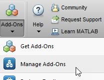
In the Add-On Manager, start the hardware setup process by clicking Setup button,
 .
.After starting, the Hardware Setup window provides instructions for configuring the support package to work with your hardware.
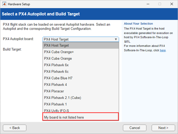
In the Select a PX4 Autopilot and Build Target screen, select
My board is not listed
                            here
.
Browse to the corresponding CMake Build target (
cubepilot_cubeorange_default) in your PX4 Firmware for building.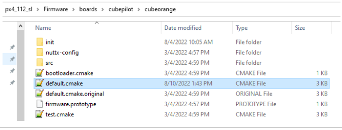
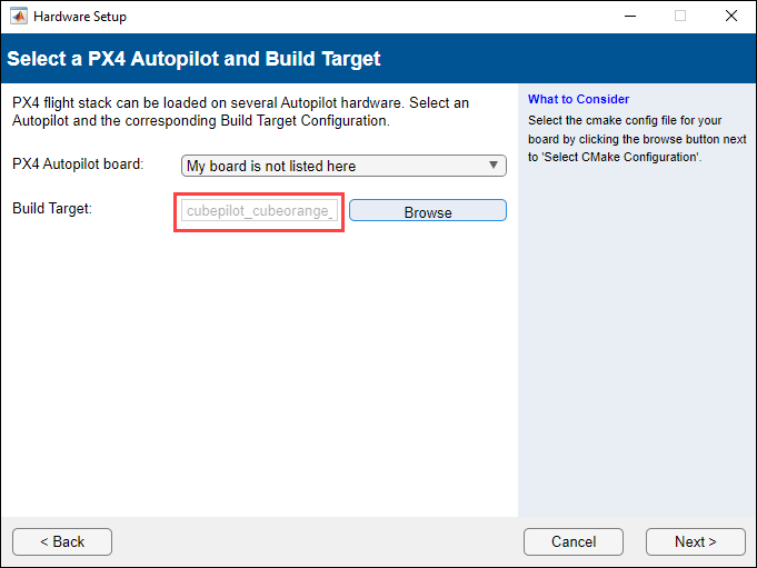
Verify the correct make command to build the firmware for Cube Orange and then click Build Firmware.
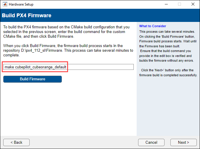
For Cube Orange, the bootloader COM Port and the main communications COM Port are different. In the Test Connection hardware setup screen, specify the Upload port in
<Enter
                                Upload Port>
text box manually and click Upload Firmware button, to upload the PX4 firmware.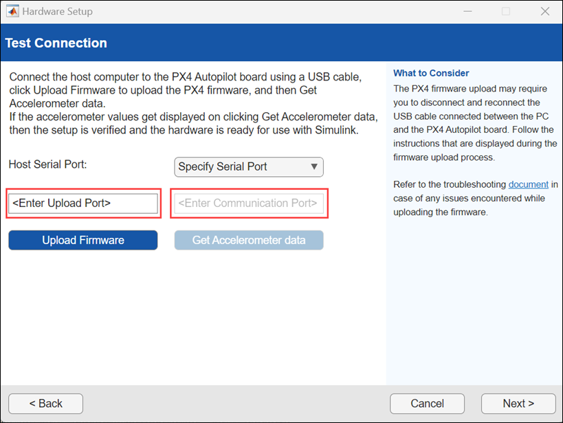
Specify the communication port and click Get Accelerometer Data to confirm that the hardware is ready for use with Simulink.
For getting Upload port and Communication port check the Device Manager, The bootloader port appears first in the Device Manager. The port shows for a few seconds and then the main communications port appears. The bootloader COM port is needed for firmware upload and the communication port is needed for MAVLink communication or Monitor and Tune simulation.
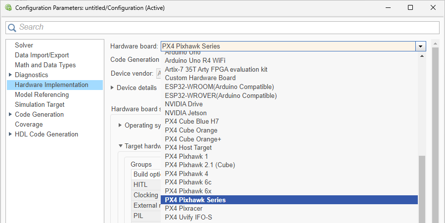
Select PX4 Pixhawk Series as the Simulink Target Hardware
After hardware setup is completed and the PX4 Firmware is successfully built for the selected build target, you can use your Cube Orange autopilot in Simulink by selecting PX4 Pixhawk® Series as Hardware board in the Simulink model configuration settings.
The selected CMake build target in hardware setup automatically appears in CMake configuration.
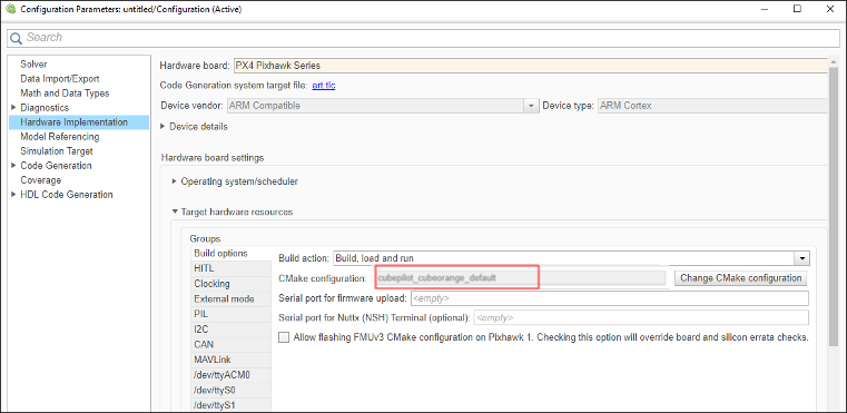
Set COM Port for Upload and Communication in Simulink
In some Cube Orange boards, the bootloader COM Port for uploading the firmware and the main communications COM Port are different. When you connect to such boards, the bootloader port appears first in the Device Manager. The port shows for a few seconds and then the main communications port appears. The bootloader COM port is needed for firmware upload and the communication port is needed for MAVLink communication or Monitor and Tune simulation.
For example, below is a snapshot of the Device Manager window when a Cube Orange is connected. After connecting, a COM port called ProfiCNC Cube (COM13) comes up under ports. This is the bootloader port needed for firmware upload. This port stays for a while after which the board loads the main Firmware and the main communication port Cube Orange PX4 (COM14) comes up. Hence, for this board COM13 is the bootloader port and COM14 is the communications port.
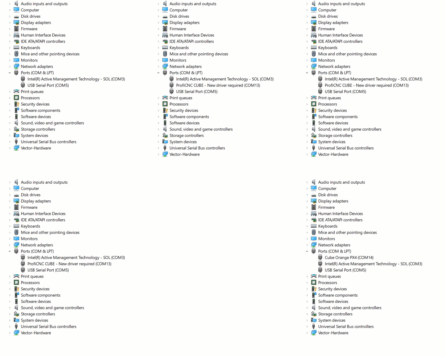
Ensure that you specify the correct COM ports for firmware upload and MAVLink communication. You will be unable to upload the firmware if you specify the communication COM port value instead of bootloader COM port value for firmware upload. In such cases, perform the following steps to set the upload and communication port correctly for a Pixhawk board in the Simulink model for different modes of simulation.
Set Bootloader COM Port for Firmware Upload and Deploy
For the Simulink model, launch the Model Settings.

A sample image of the default settings for hardware implementation is shown here.

Enter the bootloader serial port in Serial Port for firmware upload (This should be the bootloader port).

Deploy the Simulink model. On the Hardware tab, in the Mode section, select Run on board and then click Build, Deploy & Start.
Set Communication COM Port for Monitor & Tune (External Mode)
Perform the settings for Build options as shown in the topic Set Bootloader COM Port for Firmware Upload and Deploy.
In External mode tab, clear the Use the same host serial port for External Mode as used for firmware upload option and mention the main communications port in Host Serial Port (this must be different from the bootloader port you mentioned earlier in Build options).

Run the model in External Mode.
Set Communication COM Port for PIL
Perform the settings for Build options as shown in the topic Set Bootloader COM Port for Firmware Upload and Deploy.
In PIL Tab, clear the Use the same host serial port for PIL as used for firmware upload option and mention the main communications port in Host Serial port (this must be different from the bootloader port you mentioned earlier in Build options).

Limitations
Connected I/O Simulation is not supported with PX4 Pixhawk Series boards.
In the MAT-file Logging on SD Card for PX4 Autopilots example, provide communication COM port as an input argument to the
getMATFilesFromPixhawkfunction. Automatic detection of COM port is not supported with Cube orange.getMATFilesFromPixhawk('px4demo_log','DeleteAfterRetrieval', true,'COMPort','COM13')