Simulating Automatic Climate Control Systems
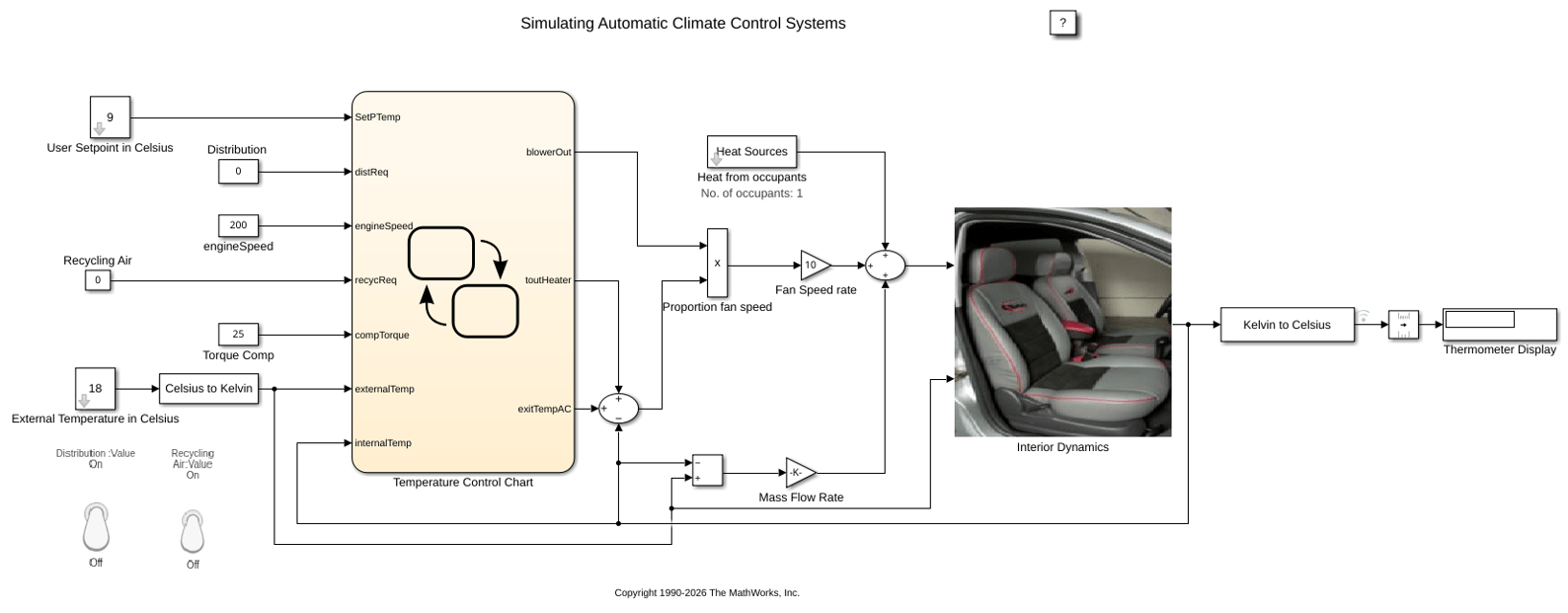
R2026bThis example shows how to simulate an automatic climate control system in a car using Simulink® and Stateflow®. In the User Setpoint in Celsius block, set the desired cabin temperature. In the External Temperature in Celsius block, set the outside temperature. The Thermometer Display block shows the temperature reading from a sensor behind the driver's head, representing the temperature the driver feels.
Stateflow Controller
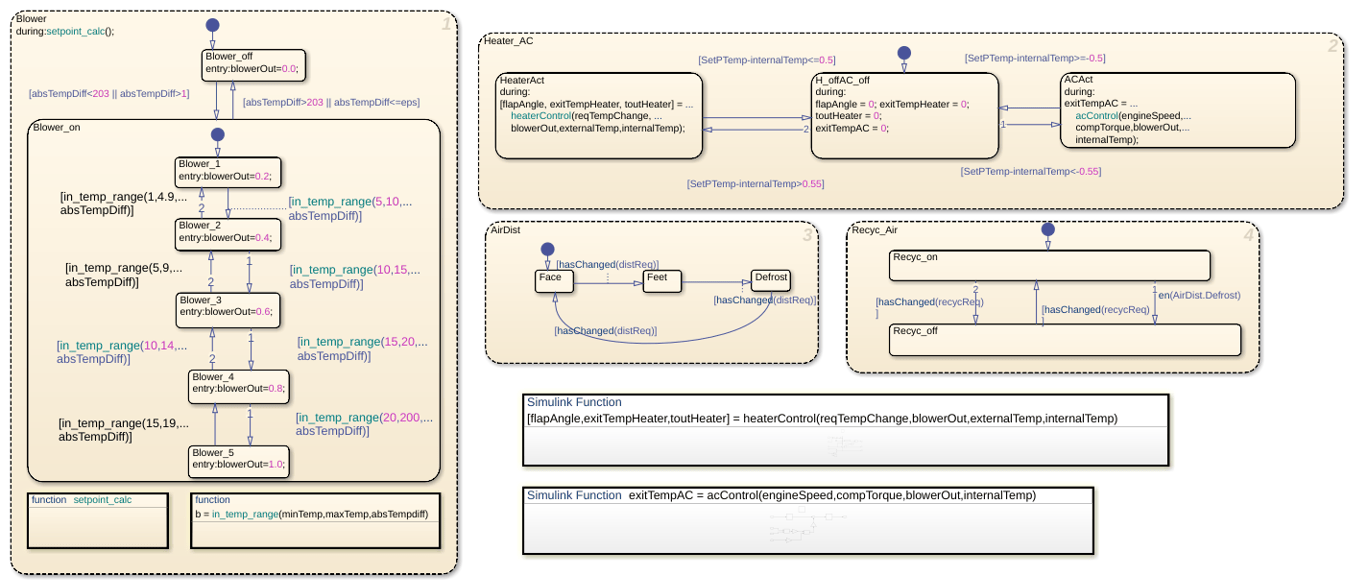
Stateflow implements the supervisory controller. To see the control logic, open the chart.
The Heater_AC state manages temperature control by transitioning between heating, idle, and cooling modes. Heating turns on when the setpoint exceeds the internal temperature by more than 0.55 ºC and turns off when the difference is 0.5 ºC or less. Similarly, cooling turns on when the internal temperature exceeds the setpoint by more than 0.55 ºC and turns off when the difference is 0.5 ºC or less. The controller uses a 0.05 ºC hysteresis band from 0.5 ºC to 0.55 ºC around the setpoint to prevent rapid switching between heating and cooling.
In the Blower state, the system adjusts the fan output based on the temperature difference. The system turns the blower off when the absolute temperature difference is below eps or too large. The blower runs only within the defined intermediate temperature range, allowing efficient and proportional airflow control during temperature regulation.
Two switches trigger the Stateflow charts that control the Air Distribution (AirDist) and Recycling Air (Recyc_Air) states. To facilitate effective window defrosting, the controller implements an internal transition within these two states. When the defrost state is active, the controller turns off the recycling air.
Heater and Air Conditioner Models
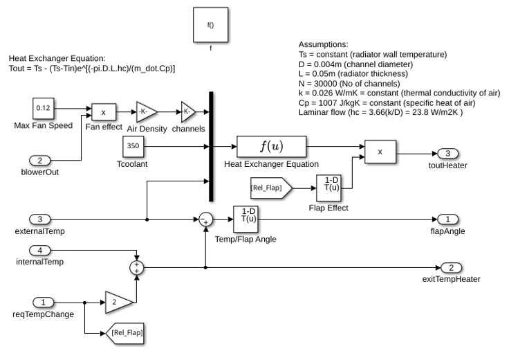
The heater model implements this heat exchange equation:
Tout = Ts - (Ts-Tin)e^[(-pi*D*L*hc)/(m_dot*Cp)]
Where:
Ts = constant (radiator wall temperature)
D = 0.004m (channel diameter)
L = 0.05m (radiator thickness)
N = 30000 (Number of channels)
k = 0.026 W/mK = constant (thermal conductivity of air)
Cp = 1007 J/kgK = constant (specific heat of air)
Laminar flow (hc = 3.66(k/D) = 23.8 W/m2K )
The models account for the heater flap. Similar to the blower operation, the greater the temperature difference between the required setpoint temperature and the current interior temperature, the greater the heating effect.
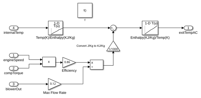
The air conditioner model implements this equation:
y*(w*Tcomp) = m_dot*(h4-h1)
Where:
y = efficiency
m_dot = mass flow rate
w = speed of the engine
Tcomp = compressor torque
h4, h1 = enthalpy
The bang-bang control of the A/C system uses the engine speed and compressor torque to determine the temperature of the air that exits the A/C. This is the heater control subsystem.
This is the acControl subsystem.
Cabin Heat Transfer
These factors affect the temperature of the air felt by the driver:
Temperature of the air exiting the vents
Temperature of the outside air
Number of people in the car
The factors are inputs into the thermodynamic model of the cabin interior. To account for the temperature of the air exiting the vents, the model calculates the difference between the vent air and the current car temperature and multiplies it by the fan speed proportion (mass flow rate). The model adds 100 W of energy per person in the car. To account for air radiating into the car from the outside, the model multiplies the difference between the outside and interior air temperature by a smaller mass flow rate.
The Thermometer Display block displays the Interior Dynamics model output. It is a reading of a temperature sensor placed behind the driver's head. If you run the simulation with the default settings, the temperature reading starts at the external temperature of 18 °C and then cools to the user setpoint of less than 9 °C.


