Multiport Switch
Select output signal based on control signal
Libraries:
Simulink /
Signal Routing
HDL Coder /
Signal Routing
Alternative Configurations of Multiport Switch Block:
Index Vector
Description
The Multiport Switch block determines which of several inputs to the block passes to the output. The block bases this decision on the value of the first input. The first input is the control input and the remaining inputs are the data inputs. The value of the control input determines which data input passes to the output.
The Multiport Switch and Index Vector blocks are alternative configurations of the same block.
Multiport Switch — Select output signal based on control signal.
Index Vector — Switch output between different inputs based on value of first input.
The table summarizes how Multiport Switch interprets the control input and determines the data input that is passed to the output.
| Control Input | Truncation | Setting for Data Port Order | Block Behavior During Simulation | |
|---|---|---|---|---|
| Indexing to Select Data Input | Out-of-Range Condition | |||
Integer value | None | Zero-based contiguous | Zero-based indexing | The control input is less than |
One-based contiguous | One-based indexing | The control input is less than | ||
Specify indices | Indices you specify | The control input does not correspond to any specified data port index. | ||
Not an integer value | The block truncates the value to an integer by rounding to zero. | Zero-based contiguous | Zero-based indexing | The truncated control input is less than
|
One-based contiguous | One-based indexing | The truncated control input is less than
| ||
Specify indices | Indices you specify | The truncated control input does not correspond to any specified data port index. | ||
For information on how the block handles the out-of-range condition, see How the Block Handles an Out-of-Range Control Input.
Multiport Switch Configured as an Index Vector Block
An Index Vector is a special
configuration of a Multiport Switch block in which you specify one
data input and the control input is zero-based. The block output is the element of
the input vector whose index matches the control input. For example, if the input
vector is [18 15 17 10] and the control input is
3, the element that matches the index of 3 (zero-based) is
10, and that becomes the output value.
To configure a Multiport Switch block to work as an Index
Vector block, set Number of data ports to
1 and Data port order to
Zero-based contiguous.
How the Block Handles an Out-of-Range Control Input
For an input with an integer value less than intmax(‘int32’), the input
is out of range when the value does not match any data port indices. For a control
input that is not an integer value, the input is out of range when the
truncated value does not match any data port indices. In
both cases, the block behavior depends on your settings for Data port for
default case and Diagnostic for default
case.
Note
If the control input is larger than intmax(‘int32’), the
block wraps the input value to an integer.
The following behavior applies only to simulation for your model.
| Data Port for Default Case | Diagnostic for Default Case | ||
|---|---|---|---|
| None | Warning | Error | |
|
|
Use the last data port and do not report any warning or error. |
Use the last data port and report a warning. |
Report an error and stop simulation. |
|
|
Use the additional data port with a |
Use the additional data port with a |
Report an error and stop simulation. |
The following behavior applies to code generation for your model.
| Data Port for Default Case | Diagnostic for Default Case | ||
|---|---|---|---|
| None | Warning | Error | |
|
|
Use the last data port. |
Use the last data port. |
Use the last data port. |
|
|
Use the additional data port with a |
Use the additional data port with a |
Use the additional data port with a |
Use Data Inputs That Have Different Dimensions
If two signals have a different number of dimensions or different dimension lengths, you can use the signals as data inputs to a Multiport Switch block. In the block dialog box, select the parameter Allow different data input sizes. In this case, the output of the block is a variable-size signal. If you do not select this parameter, the block generates an error.
For more information about the parameter, see Allow different data input sizes (Results in variable-size output signal). For more information about variable-size signals, see Variable-Size Signal Basics.
Rules That Determine the Block Behavior
You specify the number of data inputs with Number of data ports.
If you set Number of data ports to 1, the block behaves as an index selector or index vector and not as a multiport switch. For more details, see Multiport Switch Configured as an Index Vector Block.
If you set Number of data ports to an integer greater than 1, the block behaves as a multiport switch. The block output is the data input that corresponds to the value of the control input. If at least one of the data inputs is a vector, the block output is a vector. In this case, the block expands any scalar inputs to vectors.
If all the data inputs are scalar, the output is a scalar.
Guidelines on Setting Parameters for Enumerated Control Port
When the control port on the Multiport Switch block is of enumerated type, follow these guidelines:
| Scenario | What to Do | Rationale |
|---|---|---|
|
The enumerated type contains a value that represents invalid, out-of-range, or uninitialized values. |
|
This block configuration handles invalid values that the enumerated type explicitly represents. |
|
The enumerated type contains only valid enumerated values. Data input ports can never get invalid values of enumerated type. |
|
This block configuration avoids unnecessary diagnostic action. |
|
The block does not have a data input port for every value of the enumerated type. |
|
This block configuration handles enumerated values that do not have a data input port, along with invalid values. |
Examples
This example shows how to use a Multiport Switch block that specifies noncontiguous integer values for data ports. The values of the indices are visible on the data port labels. You do not have to open the block dialog box to determine which value maps to each data port.

When you set Data port for default case to Additional data port, an extra port with a * label appears. This port corresponds to the default case, which applies when the control input does not match the data port indices 3, 5, 0, or 18. When that happens in this example, the Multiport Switch block outputs a value of 1.
This example shows a Multiport Switch block that uses zero-based indexing for contiguous ordering of three data ports.

The indices are visible on the data port labels. You do not have to open the block dialog box to determine if the data ports use zero-based or one-based indexing.
When you set Data port for default case to Last data port, the last data port includes a * on the label (in this case, the label is *,2). The comma after the * indicates that the data port index has a value. This port corresponds to the default case, which applies when the control input does not match the data port indices. In this example, the Multiport Switch block outputs a value of -0.1 when the control input does not match the data port indices of 0, 1, or 2.
The sf_semantics_hotel_checkin model uses a Multiport Switch block. This block uses one-based indexing for contiguous ordering of three data ports.
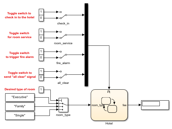
When you increase the size of the block icon, the indices are visible on the data port labels. You do not have to open the block dialog box to determine whether the data ports use zero-based or one-based indexing.
The sldemo_fuelsys model uses a Multiport Switch block in the fuel_rate_control/fuel_calc/feedforward_fuel_rate subsystem. This block uses the enumerated type sld_FuelModes to specify three data port indices: LOW, RICH, and DISABLED.

When you set Data port for default case to Last data port, the last data port includes a * on the label. The comma and ellipsis after the * indicate that the data port index has a value. This port corresponds to the default case, which applies when the control input does not match the data port indices LOW, RICH, or DISABLED. In this case, the Multiport Switch block outputs a value of 0.
Extended Examples

Model Fault-Tolerant Fuel Control System
Combine Stateflow® and Simulink® capabilities to model hybrid systems. This type of modeling is particularly useful for systems that have numerous possible operational modes based on discrete events. Traditional signal flow is handled in Simulink while changes in control configuration are implemented in Stateflow. The model described in this example represents a fuel control system for a gasoline engine. The system is robust in that it detects individual sensor failures, and the control system is dynamically reconfigured for uninterrupted operation.
Limitations
If the data inputs to the Multiport Switch block are buses, the element names of both buses must be the same. Using the same element names ensures that the output bus has the same element names no matter which input bus the block selects. To ensure that your model meets this requirement, use a bus object to define the buses and set the Element name mismatch diagnostic to
error.For arrays of buses, Number of data ports must be set to a value of
2or greater.
Ports
Input
Output
Parameters
Block Characteristics
Data Types |
|
Direct Feedthrough |
|
Multidimensional Signals |
|
Variable-Size Signals |
|
Zero-Crossing Detection |
|
Alternative Configurations
Extended Capabilities
HDL Coder™ provides additional configuration options that affect HDL implementation and synthesized logic.
This block has one default HDL architecture.
| General | |
|---|---|
| CodingStyle | Specify whether to generate HDL code with case statements or if-else statements. By default, HDL Coder generates if-else statements. See also CodingStyle (HDL Coder). |
| ConstrainedOutputPipeline | Number of registers to place at
the outputs by moving existing delays within your design. Distributed
pipelining does not redistribute these registers. The default is
|
| InputPipeline | Number of input pipeline stages
to insert in the generated code. Distributed pipelining and constrained
output pipelining can move these registers. The default is
|
| OutputPipeline | Number of output pipeline stages
to insert in the generated code. Distributed pipelining and constrained
output pipelining can move these registers. The default is
|
| SynthesisAttributes |
Specifies the synthesis attributes for the blocks and block output signals in the model. The generated HDL code contains these attributes. For more information, see SynthesisAttributes (HDL Coder). |
| Native Floating Point | |
|---|---|
| LatencyStrategy | Specify whether to map the blocks in your design to
|
This block supports code generation for complex signals.
You can specify the data port indices to the input port using specify indices
mode. To configure the Multiport Switch block with specify indices mode, set the
Data port order block parameter to Specify
indices. Then, enter the port indices in the Data
port indices block parameter. For a model targeted for HDL code
generation, you can use these input data types for the control input in a
specify indices mode:
Fixed-point and floating-point types
Signed and unsigned integer types
Enumerated types
Vector, matrix, and bus types
You can set Data port order to Specify indices, and enter enumeration values for the Data port indices. For example, you can connect the Enumerated Constant block to the Multiport Switch control port and use the enumerated types as data port indices.

You must avoid using of NaN or out of range values at the
control port. It can cause simulation mismatch in the validation model.