Modeling Two-Phase Fluid Systems
Blocks in the Two-Phase Fluid library model fluids that can undergo phase changes. Two-phase fluids react to temperature or pressure in the model by vaporizing or condensing. Blocks in the two-phase fluid domain can model liquid, vapor, a combination of both, or supercritical fluid.
Using the Two-Phase Fluid Library
Two-phase fluid blocks assume that the liquid-vapor mixture is homogeneous and that there is no velocity difference between the fluid phases. The two-phase fluid domain does not model stratified liquid and vapor flow and treats the mixture as a single fluid. The one exception is the Receiver Accumulator (2P) (Simscape Fluids) block in the Simscape™ Fluids™ library, which explicitly models the separation of the liquid and the vapor.
The Across variables are absolute pressure and specific internal energy, and the Through variables are mass flow rate and energy flow rate. These variables result in a pseudo-bond graph because the product of pressure and mass flow rate is not power.
Two-phase fluid blocks do not model choked flow. If you need to model choked flow, insert the Interface (2P-G) (Simscape Fluids) block and use the gas domain to model the choked flow. The Interface (2P-G) (Simscape Fluids) block is available in the Simscape Fluids library.
Intended Applications
The Two-Phase Fluid library contains basic elements, such as orifices, chambers, and hydromechanical converters, as well as sensors and sources. Use these blocks to create models for applications that require a liquid to undergo phase changes, such as:
HVAC systems
Refrigeration cycles
Automotive cooling systems
Power generation
If you have a Simscape Fluids license, you can use more complex blocks such as heat exchangers, fluid machines, and valves. For more information, see Two-Phase Fluid Library (Simscape Fluids).
Two-Phase Fluid Properties
Two-phase fluid properties, such as temperature and viscosity, are a function of
pressure and internal energy. Use the Two-Phase Fluid Properties
(2P) block to specify the two-phase fluid properties for your
network. You can use the twoPhaseFluidTables function to
generate fluid properties for the block. For more information on generating fluid
properties for a specific working fluid, see Manually Generate Fluid Property Tables.
If you have a Simscape Fluids license, you can use the Two-Phase Fluid Predefined Properties (2P) (Simscape Fluids) block to specify a predefined working fluid in a two-phase fluid system. Use this block to select the working fluid from a list that includes water, popular refrigerants, carbon dioxide, and other fluids at the specified ranges of pressure and temperature.
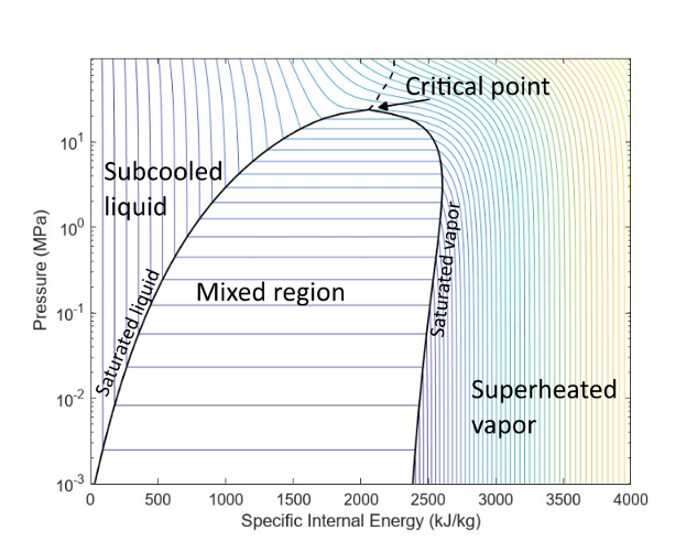
You can use the Two-Phase Fluid Properties (2P) block to visualize a p-h diagram of the working fluid. To plot the data, right-click the Two-Phase Fluid Properties (2P) block and select Foundation Library > Plot Fluid Properties (Contours). This figure shows the p-h diagram for the default two-phase fluid with the fluid regions labeled.

Fluid under the saturation dome is a mix of vapor and liquid. The contour lines in the plot denote the fixed temperature values. As you move to the right under the dome along a temperature contour, the enthalpy and vapor quality increase while the pressure stays fixed. The left leg of the dome is the saturated liquid curve, while the right leg is the saturated vapor curve. These two curves meet at the critical point. Above the critical point is the supercritical region where vapor and liquid no longer exist as separate phases.
Some two-phase fluid blocks define internal conditions by the degree of subcooling
or superheating. For example, in the Reservoir (2P)
block, you can set Reservoir energy specification to
Degree of subcooling or Degree of
superheating to use the Reservoir subcooling
or Reservoir superheating parameter, respectively, to specify
the reservoir energy. Both of these parameters have units of change in temperature
and define the distance in terms of temperature from the saturation dome. The
subcooling is the distance to the left from the left curve, or the difference
between the liquid saturation temperature and the fluid temperature. The
superheating is the distance to the right from the right curve, or the difference
between the fluid temperature and the vapor saturation temperature.
Blocks with Two-Phase Fluid Volume
Certain blocks in the Two-Phase Fluid library model fluid volume. These blocks use an internal node to represent the two-phase fluid volume inside the block. This internal node is not visible, but you can access its parameters and variables using Simscape data logging. For more information, see About Simulation Data Logging.
These blocks model fluid volume. In the case of Controlled Reservoir (2P) and Reservoir (2P) blocks, the block models the volume as infinitely large.
| Block | Two-Phase Fluid Volume |
|---|---|
| Constant Volume Chamber (2P) | Finite |
| Pipe (2P) | Finite |
| Rotational Mechanical Converter (2P) | Finite |
| Translational Mechanical Converter (2P) | Finite |
| Reservoir (2P) | Infinite |
| Controlled Reservoir (2P) | Infinite |
The other components in the Two-Phase Fluid library have arbitrarily small fluid volumes, so that the fluid entering the component spends negligible time inside the component before exiting. These components are quasi-steady-state and do not have an internal node.
Cross-Sectional Area at Block Ports
Many blocks in the two-phase fluid domain let you specify the cross-sectional area at the inlet and outlet ports as a block parameter. Specify the same cross-sectional area for ports that are connected together. For example, if you connect port A of a Constant Volume Chamber (2P) block to a Pipe (2P) block, set the Cross-sectional area at port A parameter of the Constant Volume Chamber (2P) block to the same value as the Cross-sectional area parameter of the Pipe (2P) block.
Differences in the connected port area can result in unexpected temperature differences, especially for high-speed flows where the Mac number is close to 1. For more information, see Specifying the Cross-Sectional Area at Ports.