Vollwellen-Brückengleichrichter
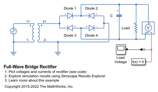
Dieses Beispiel zeigt einen idealen Wechselstromtransformator mit Vollwellen-Brückengleichrichter. Er wandelt 120 Volt Wechselstrom in 12 Volt Gleichstrom um. Der Transformator hat ein Windungsverhältnis von 14 und reduziert die Versorgungsspannung auf 8,6 Veff, d. h. 8,6*sqrt(2) = 12 Volt Spitze-Spitze. Die Kombination aus Vollwellen-Brückengleichrichter und Kondensator wandelt diese dann in Gleichstrom um. Der Widerstand steht für eine typische Last.
Das Modell kann verwendet werden, um die Größe des für eine bestimmte Last erforderlichen Kondensators festzulegen. Bei einer bestimmten Kondensatorgröße nimmt die Welligkeit der Gleichspannung zu, wenn der Lastwiderstand erhöht wird. Das Modell kann auch zur Ansteuerung einer Anwendungsschaltung verwendet werden, um die Auswirkung der Welligkeit zu beurteilen.
Modell

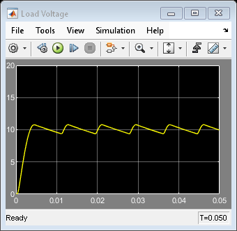
Simulationsergebnisse von Scopes

Simulationsergebnisse der Simscape-Protokollierung
Das Diagramm „Bridge Rectifier Voltages and Currents“ (Spannungen und Ströme des Brückengleichrichters) zeigt, wie Wechselspannung in Gleichspannung umgewandelt wird. Die dunkelblaue Linie ist die Wechselspannung auf der Quellenseite der Brücke. Der Strom kann auf zwei Wegen durch die Diodenbrücke fließen. Die alternierenden Spitzen durch die Dioden 1 und 4 und die Dioden 2 und 3 zeigen, dass der Strom, der den Kondensator erreicht, auch dann in dieselbe Richtung fließt, wenn sich die Polarität der Spannung ändert. Die Welligkeit der Lastspannung entspricht dem Laden und Entladen des Kondensators.
