Gassysteme
Erkunden Sie Beispiele, die die Modellierung, Regelung und Simulation von Gassystemen veranschaulichen.
Enthaltene Beispiele

Pneumatischer Betätigungskreis
Dieses Beispiel zeigt, wie die Gaskomponenten der „Foundation“-Bibliotheken zur Modellierung eines geregelten pneumatischen Aktors verwendet werden können. Das Wegeventil ist ein maskiertes Subsystem („Directional Valve“), das aus den „Variable Local Restriction (G)“-Blöcken erstellt wurde, um das Öffnen und Schließen der Durchflusswege zu modellieren. Der doppeltwirkende Aktor ist ein maskiertes Subsystem („Double-Acting Actuator“), das aus den „Translational Mechanical Converter (G)“-Blöcken erstellt wurde, um die Schnittstelle zwischen dem Gasnetz und dem Netz für mechanische Translation zu modellieren.

Pneumatic Motor Circuit
How a pneumatic vane motor can be modeled using the Simscape™ language. The Pneumatic Motor component is built using the Simscape Foundation gas domain. It inherits from the foundation.gas.two_port_steady base class, which contains common equations that implement the upwind energy flow rate and the gas properties at the ports. The Pneumatic Motor subclass implements equations that describe behaviors specific to the component, such as the motor torque and flow rate characteristics and the mass and energy balance. The Pneumatic Motor block is inserted into the model using the Simscape Component block without the need to generate a separate library.
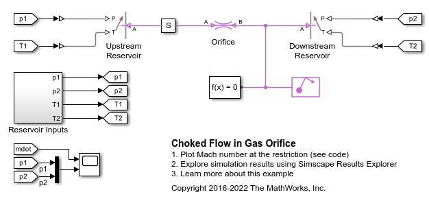
Gedrosselte Strömung in einer Gasblende
Dieses Beispiel zeigt das Drosselverhalten einer Gasblende, die durch den Block „Local Restriction“ (G) modelliert wird. Die Blöcke „Controlled Reservoir“ (G) werden verwendet, um kontrollierte Druck- und Temperatur-Randbedingungen vom Subsystem „Reservoir Inputs“ aus einzurichten, um die Gasblende zu testen.

Brayton-Kreisprozess (Gasturbine) mit benutzerdefinierten Komponenten
Dieses Beispiel modelliert ein auf dem Brayton-Kreisprozess basierendes Gasturbinen-Hilfstriebwerk (APU). Die Blöcke „Compressor“ (Verdichter) und „Turbine“ sind benutzerdefinierte Komponenten, die auf der Simscape™-Bibliothek „Foundation > Gas“ basieren. Der Energieeintrag in das System wird durch die Wärmezufuhr in die Verbrennungsanlage dargestellt; die tatsächliche Verbrennungschemie wird nicht modelliert. Verdichter und Turbine sind über eine einzelne Welle gekoppelt, so dass die Kraft der Turbine den Verdichter antreibt. Die APU ist als Freiturbine ausgeführt, die den Abgasstrom weiter entspannt, um Nutzleistung zu erzeugen.
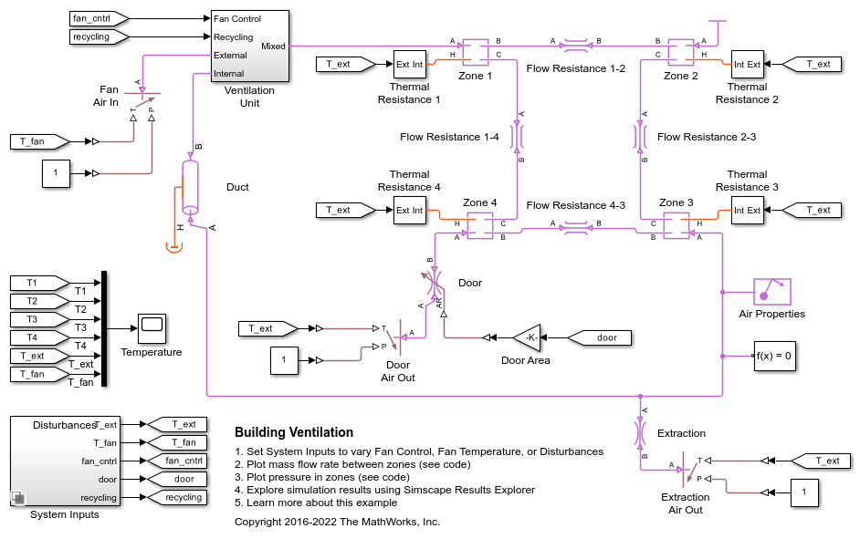
Gebäudebelüftung
In diesem Beispiel wird ein Belüftungskreislauf in einem Gebäude modelliert. Das Luftvolumen innerhalb des Gebäudes ist in vier Zonen unterteilt. Die Belüftungsanlage bläst kühle Luft in Zone 1 und saugt Luft aus Zone 3 ab. Die abgesaugte Luft kann optional wieder in Zone 1 zurückgeführt werden. In Zone 4 kann eine Tür geöffnet werden, um Luft in die Atmosphäre abzuleiten.
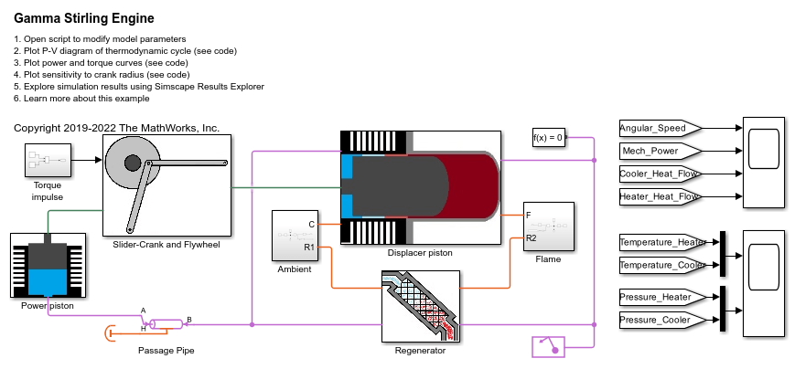
Gamma Stirling Engine
Model a Gamma Stirling engine using gas, thermal, and mechanical Simscape™ components and domains.
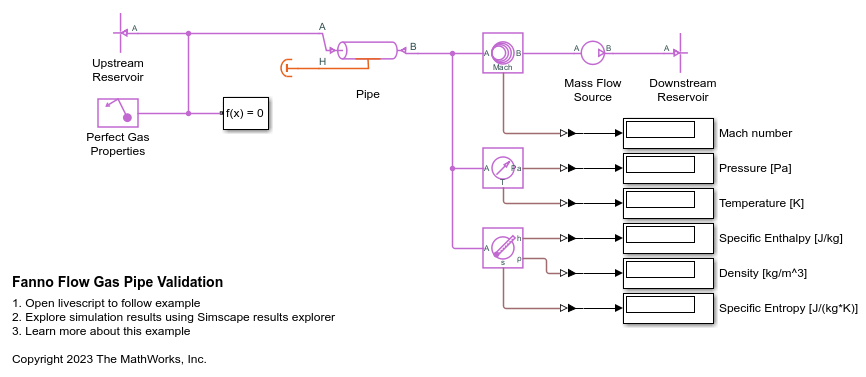
Fanno Flow Gas Pipe Validation
The Fanno flow model is an analytical solution of an adiabatic (perfectly insulated) compressible perfect gas flow through a constant area pipe with friction. This example shows a comparison and validation of the Simscape™ Pipe (G) block against the Fanno flow model. While you typically need empirical data to validate a block over a range of scenarios, it may still be useful to perform limited validation against analytical models for specific scenarios. This is because the theory and derivation behind the analytical model may provide more insight into where the block works well and how to address limitations. The comparison shows that, for short to moderate pipe lengths, the Simscape pipe model agrees well with the Fanno flow model. For long pipe lengths, a segmented pipe model agrees well with the Fanno flow model.

Compressor Map with Scattered Lookup
Gas flow through a compressor which is modeled using a simple controlled mass flow rate source. The compressor map that governs this mass flow rate is modeled using the PS Scattered Lookup (2D) block whose data coordinates are the pressure ratio (Pa/Pa) and the engine RPM, and the output is the mass flow rate (kg/s). The scattered lookup block performs delaunay triangulation on the input data (which is shown in plots below), and uses this to interpolate and calculate the mass flow rate based on the input. Scattered lookup allows modeling of the compressor even if the data provided is in an unstructured format.