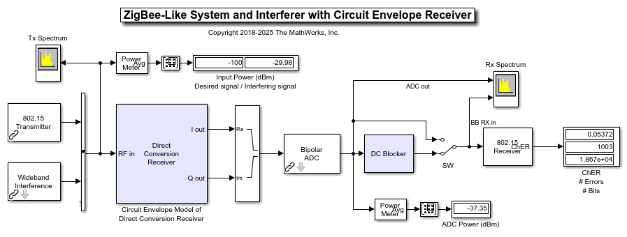
Integrate Antenna Into RF Receiver
This example shows how to:
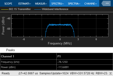
Integrate a simple dipole antenna into the system-level model of the RF receiver and understand the impact of polarization mismatch.
Design a dual polarized antenna, analyze its performance using EM analysis, and integrate it in the system-level model of the RF receiver.
Design a Wilkinson combiner and integrate it together with the dual polarized antenna into the system-level model.
Integrate Dipole Antenna into RF Receiver
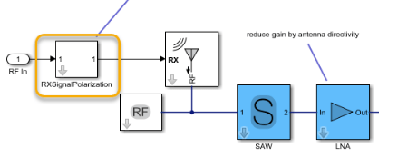
An dipole antenna is added to the RF receiver which was designed in step 4 of the Top-down design of an RF receiver example. To add an antenna into your receiver, insert an Antenna block from the RF Blockset Circuit Envelope library.
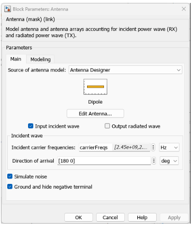
Open the mask of the Antenna block and configure it as following:
Select Input Incident wave to ensure that the antenna operate in receiving mode.
Set the Incident carrier frequencies to
carrierFreqsand select the units toHz.Set the Source of the antenna model to be
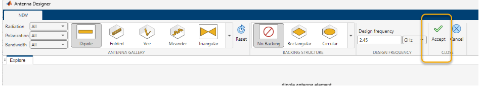
Antenna Designerand click the Create Antenna button to open the Antenna Designer app.
In the Antenna designer app, design a dipole antenna at the operating input frequency or the design frequency of 2.45 GHz and click Accept .
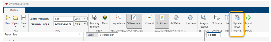
Analyze the antenna S-parameters and far-field radiation pattern. Click on Update Block and return to the Antenna block. Select Apply and then OK.
This configures the Antenna block.
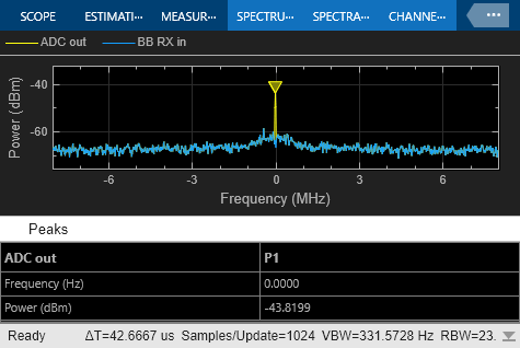
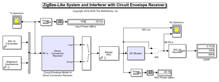
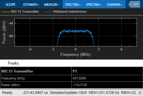
Connect the Antenna block to the RF Receiver and run the simulation. Open the mask parameters of the subsystem RXSignalPolarization, and verify the ChER in the following scenario:
Polarization Interferer = [1 0], with and without DC offset removal
Polarization Interferer = [0 1], with and without DC offset removal
Open the resulting integrated model:
sobj = sparameters('SAW_Filter_Data.s2p');
open_system('antenna_integration.slx')
w = warning('off','all');
sim('antenna_integration.slx')
warning(w)
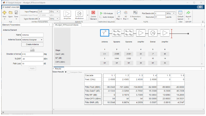
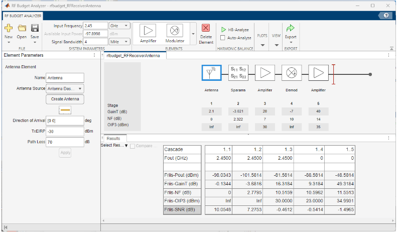
The dipole is a linearly polarized antenna along the vertical plane, hence incoming signals with horizontal polarization are not received. You can also verify the updated budget including the Antenna block. Observe that to maintain the output power consistent with the initial budget, the amplifier gain was reduced by 2 dB, the same amount as the antenna directivity gain.
rfBudgetAnalyzer('rfbudget_RFReceiverAntenna.mat')
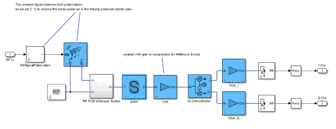
Integrate Crossed Polarized Dipole Antenna and Wilkinson Combiner
Design a dipole crossed antenna and a Wilkinson combiner to merge the two polarization components of the incoming signal. Notice that the feed network of the antenna must implement a 90 degrees relative phase shift. The antenna and the Wilkinson combiner are integrated in the RF receiver.
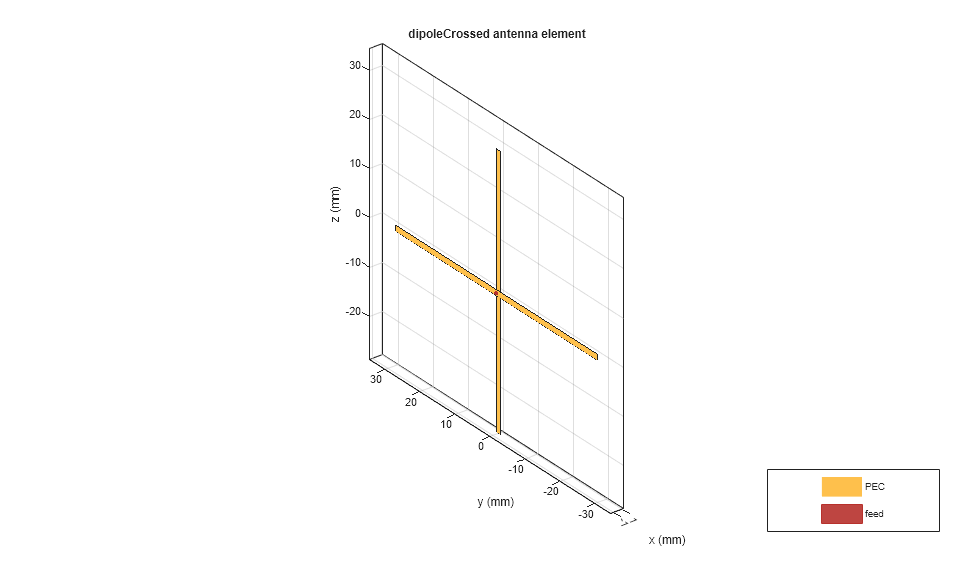
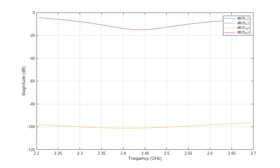
Design the crossed dipole antenna using the dipoleCrossed object that operates at the desired center frequency.
Xdipole = design(dipoleCrossed, 2.45e9);
Xdipole.Tilt = 45;
figure; show(Xdipole);
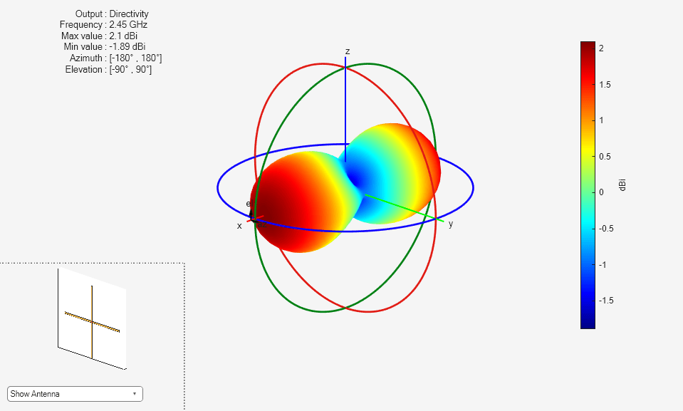
% Visualize the far field radiation pattern.
figure; pattern(Xdipole,2.45e9);
Visualize the S-parameters.
sparamXdipole = sparameters(Xdipole, (2205:24.5:2695)*1e6);
figure; rfplot(sparamXdipole);
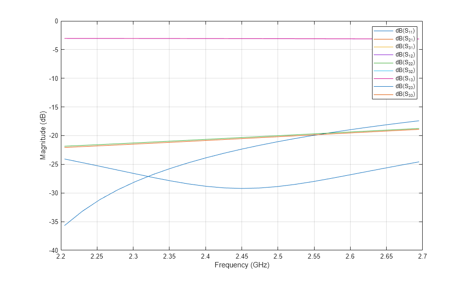
Design the Wilkinson splitter using the wilkinsonSplitter to operate at the desired center frequency. The Wilkinson splitter in this receiver will be used as a signal combiner.
wilkCombiner=design(wilkinsonSplitter, 2.45e9);
show(wilkCombiner);

Analyze and visualize the S-parameters.
sparamWilkinson=sparameters(wilkCombiner, (2205:24.5:2695)*1e6);
figure; rfplot(sparamWilkinson);
Save the S-parameter as a Touchstone file.
rfwrite(sparamWilkinson,'wilkinsonSplitterSparams.s3p')
Open the model and verify the ChER. In order to properly combine the signals at the 2 antenna ports you need to include a 90 degrees phase shift on one of the combiner branches.
open_system('RFReceiverWithXdipole.slx')
w = warning('off','all');
sim('RFReceiverWithXdipole.slx')
warning(w)
% The additional insertion loss of the Wilkinson combiner contributes to
% additional noise and degrades the available SNR.
Verify the updated budget including the losses of the Wilkinson combiner. For this, you need to identify the respective 2 port S-parameters of the combiner. Notice that the SNR is now reduced compared to the original budget and the total noise figure exceeds 14 dB.
rfwrite(snp2smp(sparamWilkinson,[1 2]),'wilkinson2ports.s2p')
rfBudgetAnalyzer('rfbudget_RFReceiverXdipole.mat')