Antenna
Model antenna or antenna array accounting for incident power wave (RX) and radiated power wave (TX)

Libraries:
RF Blockset /
Circuit Envelope /
Elements
Description
Model an antenna or antenna array using the Antenna block. Use this block to:
Convert a Simulink® input of an incident power wave vector into RF Blockset™ voltage signal at the antenna or antenna array ports.
Convert current at RF Blockset antenna or antenna array ports to a Simulink output of a radiated power wave vector.
Introduce antenna impedance into an RF system.
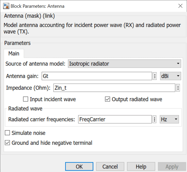
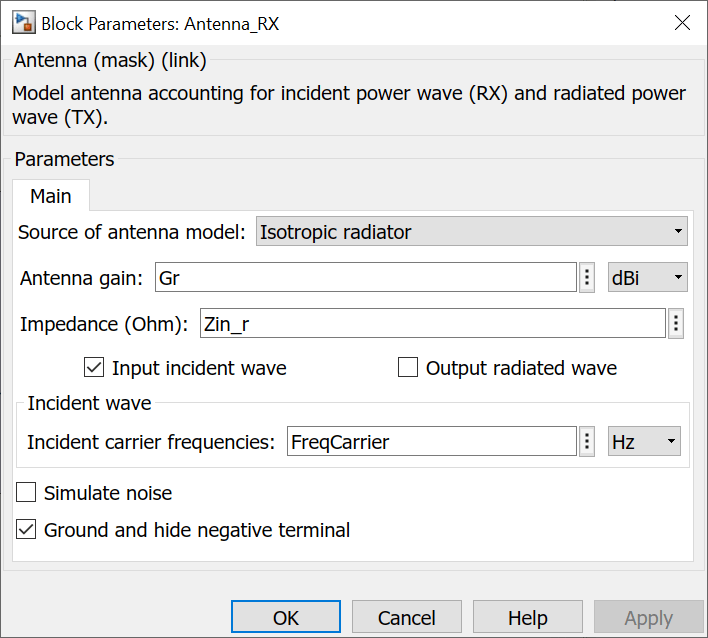
By default, the antenna block is an isotropic radiator producing a Simulink output signal. For an isotropic radiator, specify the gain and impedance of the antenna in the block parameters. The Radiated carrier frequencies parameter is a set of carrier frequencies over-which the Antenna block creates the radiated power wave. For more information, see Radiated Wave and Incident Wave.
The Antenna block mask icons are dynamic: The icons show the current state
of the noise parameter, indicate if you have specified an antennaarray object
in the Antenna object
parameter, and update the number of ports based on the number of elements in the
antennaarray object. This table shows how the block icons vary based on the
state of the Simulate noise
and Antenna object
parameters.
| Antenna object | Simulate noise: on | Simulate noise: off |
|---|---|---|
| Antenna Catalog Objects |
|
|
| Antenna Array Catalog Objects |
|
|


Examples
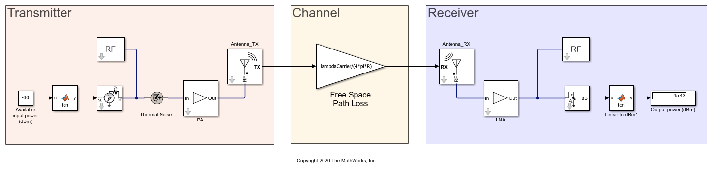
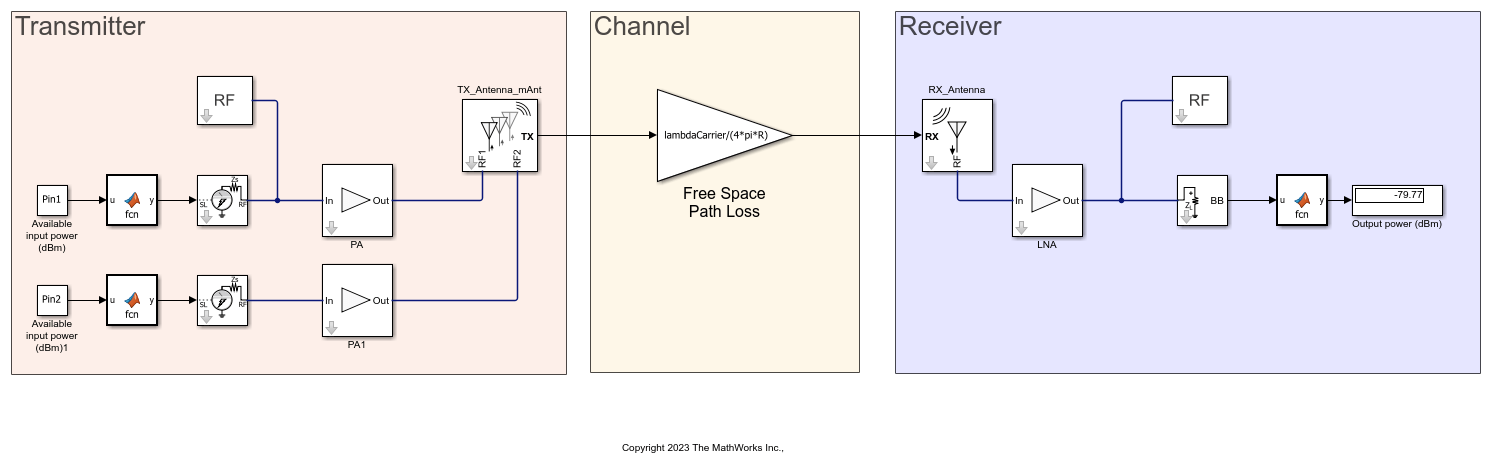
Use the Antenna block to incorporate the effect of an antenna into an RF simulation. In this model, a single tone is fed to the transmitter and the power of the received signal at the output of the receiver is calculated.
ans =

  logical

   1
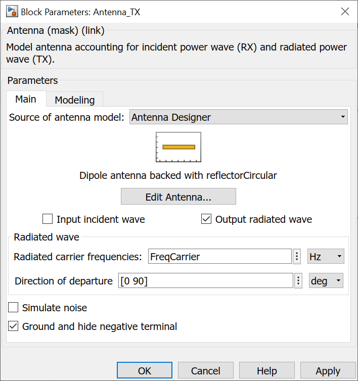
Set the Antenna_TX and Antenna_RX blocks to be isotropic radiators with the following parameters:
The following values are set upon loading the model:
R=100[m]FreqCarrier=5.0[GHz]Gt=Gr=7.9988[dBi]Zin_t=Zin_r=56.2947 - 4.2629i[Ohm]
where the antenna gains and impedances were calculated beforehand from dipoles backed by circular reflectors.
With Antenna Toolbox™, it is possible to design the antenna using the Antenna Designer app invoked directly from the block. To do so, change the choice of Source of the antenna model to Antenna Designer and press the Create antenna button. Within the Antenna Designer app, create a new antenna, choose Dipole from the Antenna Gallery, Circular from the Backing Structure Gallery in the app toolstrip and select Accept. Note that the design frequency was prepopulated with the RF system frequency of 5 GHz.
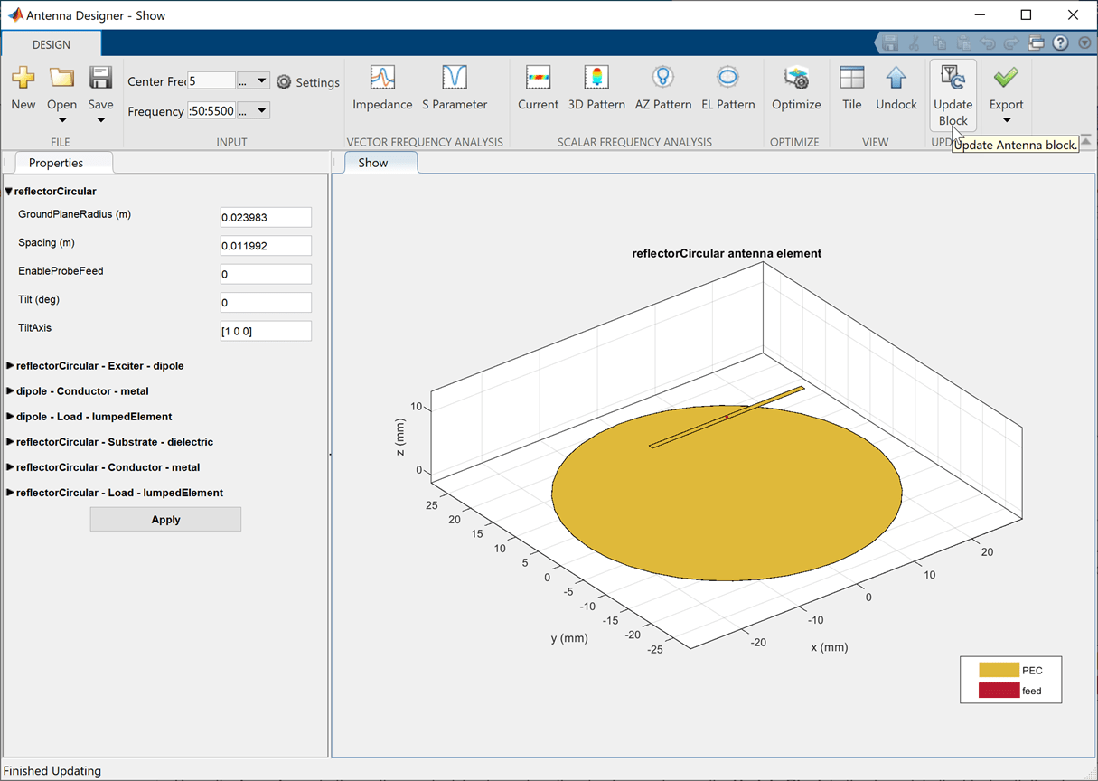
Select the Impedance button in the app toolstrip to analyze the structure and select the Update Block button to update the block with the chosen antenna. Note that the Antenna block requires that the designed antenna be analyzed for at least one frequency in the Antenna Designer app before updating and using it in the block.
In the Antenna_TX block mask parameter dialog box, change the default Direction of departure to 0 degrees in azimuth and 90 degrees in elevation:
Repeat the above steps to design Antenna_RX. However, the receiving antenna needs to be rotated to face the transmitting antenna. To do so, in the Antenna Properties panel of the Antenna Designer app, set Tilt to 180 degrees. Again, select the Impedance button and then press the Update Block button to update the block. In the Antenna_RX block mask parameter dialog box, change the Direction of arrival to 180 degrees in azimuth and -90 degrees in elevation. – 90-degree elevation is chosen since the radiated signal that was transmitted in the positive z direction in the coordinate system of the transmitter, is now arriving from the negative z direction in the coordinate system of the receiver. Azimuth is set to 180 degrees to align vector fields of the transmitter and receiver antennas.
Run the model again, and note that the output power remained almost exactly the same. This is since the original gain and impedance values used for the isotropically radiating antenna in the beginning were calculated from the same antennas and spatial settings. However, it is now possible to change the antenna properties and observe the effect on the output power in the model. For example: Select the 'Edit Antenna' button in the Antenna_TX block mask parameter dialog box to reopen the Antenna Designer app. In the Antenna Properties panel of the Antenna Designer app, change Tilt to 30 degrees and the TiltAxis to [0 1 0]. Select the Impedance button and then press the Update Block button to update the block. Rerun the model to observe reduction of 2.5 dB in the output received power due to the mismatch in antenna orientation.
Since R2023b
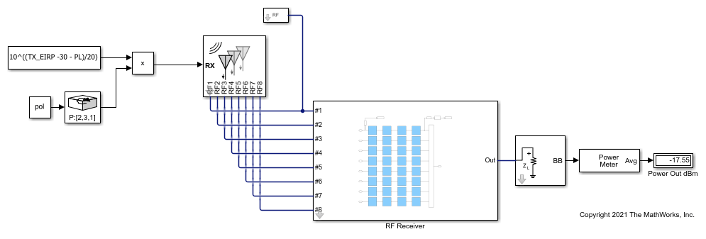
This example shows how to use measuredAntenna object in the Antenna block to model a measured antenna or array characterized by means of its S-parameters and frequency dependent far-field radiation pattern including both polarization components. The measuredAntenna object lets you replace the physical antennas from the antenna catalog with measured field data of the antenna. This example extracts data from a linear array to create a measuredAntenna object using hcreate_mAnt helper function.
System Configuration
Define the carrier frequency in Hz and set it in these parameters:
Radiated carrier frequency parameter in the Transmit Antenna block
Incident carrier frequency parameter in the Receiver Antenna block
Carrier frequencies parameter in the Inport and Outport blocks
FreqCarrier = 5e9;
Define gain for the Gain block. This Gain block acts as a free-space path-loss channel.
lambdaCarrier = physconst('lightspeed')/FreqCarrier; %[m]
Define the input impedance of the low noise amplifier (LNA) in ohms.
Zin_r =71.3819 - 1j*2.1795;
Define the available input power in dBm for the two RF transmitter chains and assign the variables to Pin 1 and Pin 2 in the Constant block.
Pin1 = -30;
Pin2 = -30;
Create a linear antenna array and extract data from it to create a measuredAntenna object. The data extracted from the linear array is a substitute of real-world measured data that can be inputted by changing the hcreate_mAnt helper function so as to read the embedded electric fields from data file.
dist = lambdaCarrier*0.5;
d1 = design(dipole,FreqCarrier);
antElems = [d1 copy(d1)];
la = linearArray('Element',antElems,'ElementSpacing',dist);
la.TiltAxis = [0 1 0];
la.Tilt = 90;
freqRange = (4.5:0.05:5.5)*1e9;
[mAnt,R] = hcreate_mAnt(la,freqRange);
Compute impedances in ohms for PA and PA1 Amplifier blocks in the transmitter.
z = impedance(la,freqRange);
z = z(freqRange==FreqCarrier,:);
Zin_t1 = z(1);
Zin_t2 = z(2);
Simulate Model
Open and simulate the measuredAnt.slx model. Observe the output power at the receiver.
open_system("measuredAnt.slx")
sim("measuredAnt.slx");
Extended Examples
Model RF Systems with Antenna Arrays Using RF Blockset Antenna Block
Use the Antenna block to design antenna arrays for an RF system.
Ports
Input
Output
Parameters
More About
The effect of free space channel between the antennas is not captured by antenna block. You can model it externally using Simulink blocks. For a free-space channel the effect is given by the transfer function:
where
λ is the wavelength modeled outside the antenna.
Ris the distance between the antennasExponential term at the end of the equation represents the time delay occurring over the distance
R.plis free-space path loss.

You can model a free-space channel using the Communications Toolbox™ Free Space Path Loss (Communications Toolbox). The effect of the power wave is described using the Friis equation. The Free Space Path Loss block operates for a single carrier frequency and is narrow band. For multiple carriers with narrow bands, the signal must be split and passed through multiple Free Space Path Loss blocks. with carrier frequencies specified in the Antenna block. When the Antenna blocks are not isotropic radiators, the output signal is a 3D array and needs to be split and reshaped before being send to the Free Space Path Loss
References
[1] Stutzman, Warren L., and Gary A. Thiele. Antenna Theory and Design. 3rd ed. Hoboken, NJ: Wiley, 2013
[2] Farr, Everett G. “Characterizing Antennas in the Time and Frequency Domains [Education Corner].” IEEE Antennas and Propagation Magazine 60, no. 1 (February 2018): 106–10. https://doi.org/10.1109/MAP.2017.2774200.
Version History
Introduced in R2020bSee Also
Amplifier | S-Parameters | Free Space Path Loss (Communications Toolbox)