serdes.CTLE
Continuous time linear equalizer (CTLE) or peaking filter
Description
The serdes.CTLE
System object™ applies a linear peaking filter to equalize a sample-by-sample input signal or
to analytically process an impulse response vector input signal. The equalization process
reduces distortions resulting from lossy channels. The filter is a real one-zero two-pole
(1z/2p) filter, unless you define the gain-pole-zero (GPZ) matrix.
To equalize the baseband signal using serdes.CTLE:
Create the
serdes.CTLEobject and set its properties.Call the object with arguments, as if it were a function.
To learn more about how System objects work, see What Are System Objects?
Creation
Description
ctle = serdes.CTLE
ctle = serdes.CTLE(Name,Value)
Example: ctle = serdes.CTLE('ACGain',5) returns a CTLE object with
gain at the peaking frequency set to 5 dB.
Properties
Unless otherwise indicated, properties are nontunable, which means you cannot change their
values after calling the object. Objects lock when you call them, and the
release function unlocks them.
If a property is tunable, you can change its value at any time.
For more information on changing property values, see System Design in MATLAB Using System Objects.
Main
CTLE operating mode, specified as 0, 1, or
2. Mode determines whether the CTLE is
bypassed or not. If CTLE is not bypassed, then Mode also
determines what transfer function is applied to the input waveform.
| Mode Value | CTLE Mode | CTLE Operation |
|---|---|---|
0 | off | serdes.CTLE is bypassed and the input waveform remains
unchanged. |
1 | fixed | serdes.CTLE applies the CTLE transfer function as
specified by ConfigSelect to the input
waveform. |
2 | adapt | If WaveType is set to 'Impulse'
or 'Waveform', then the Init subsystem calls to the
serdes.CTLE. The serdes.CTLE determines
the CTLE transfer function to maximize the performance metric as specified
by the PerformanceCriteria property and applies the
transfer function to the input waveform for time domain simulation. This
optimized transfer function is used by the CTLE for entire time domain
simulation. For more information about the Init subsystem, see Statistical Analysis in SerDes Systems |
If WaveType is selected as
'Sample', then serdes.CTLE operates in
the fixed mode. |
Data Types: double
Select which slice, family, or corner of a 3-D GPZ matrix to use during CTLE configuration.
You must set Specification to GPZ to
effectively use SliceSelect. Depending on how many slices are
available in your GPZ matrix, you can then select the slice you are interested in from
a zero-based index.
You cannot use GPZ for a given slice and the peaking gain, DC gain, or AC gain for another slice.
Data Types: double
Select which member of the transfer function family to apply in fixed mode, specified as a real integer scalar.
Example: ctle = serdes.CTLE('ConfigSelect',5,'Specification','DC Gain and
Peaking Gain') returns a CTLE object that selects the 6-th element of the
DCGain and PeakingGain vector to apply to the
filter transfer function.
Data Types: double
Defines which inputs will be used for the CTLE transfer function family. There are
five inputs which can be used to define the CTLE transfer function family:
DCGain, PeakingGain,
ACGain, PeakingFrequency, and
GPZ.
You can define the CTLE response from any two of the three gains and peaking frequency or you can define the GPZ matrix for the CTLE.
Select
'DC Gain and Peaking Gain'to specify CTLE response fromDCGain,PeakingGain, andPeakingFrequency.'DC Gain and AC Gain'to specify CTLE response fromDCGain,ACGain, andPeakingFrequency.'AC Gain and Peaking Gain'to specify CTLE response fromACGain,PeakingGain, andPeakingFrequency.'GPZ Matrix'to specify CTLE response fromGPZ.
Data Types: char
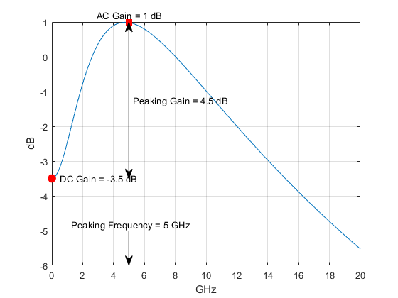
Approximate frequency at which CTLE transfer function peaks in magnitude,
specified as a scalar or a vector in Hz. If specified as a scalar, it is converted to
match the length of ACGain, DCGain, and
PeakingGain by scalar expansion. If specified as a vector, then
the vector length must be the same as the vectors in ACGain,
DCGain, and PeakingGain.
Data Types: double
Gain at zero frequency for the CTLE transfer function, specified as a scalar or a
vector in dB. If specified as a scalar, it is converted to match the length of
PeakingFrequency, ACGain, and
PeakingGain by scalar expansion. If specified as a vector, then
the vector length must be the same as the vectors in
PeakingFrequency, ACGain, and
PeakingGain.
Data Types: double
Peaking gain, specified as a vector in dB. It is the difference between
ACGain and DCGain for the CTLE transfer
function. If specified as a scalar, it is converted to match the length of
PeakingFrequency, ACGain, and
DCGain by scalar expansion. If specified as a vector, then the
vector length must be the same as the vectors in
PeakingFrequency, ACGain, and
DCGain.
Data Types: double
Gain at the peaking frequency for the CTLE transfer function, specified as a
scalar or vector in dB. If specified as a scalar, it is converted to match the length
of PeakingFrequency, DCGain, and
PeakingGain by scalar expansion. If specified as a vector, then
the vector length must be the same as the vectors in
PeakingFrequency, DCGain, and
PeakingGain.
Data Types: double
Gain pole zero, specified as a matrix. GPZ explicitly defines
the family of CTLE transfer functions by specifying the DCGain
(dB) in the first column and then poles and zeros in alternating columns. The poles
and zeros are specified in Hz. Use the argument ConfigSelect with
zero-based index to select filters defined by rows of the GPZ matrix.
The serdes.CTLE
System object only allows repeated poles or zeros when the
FilterMethod is set to Cascaded. Complex
poles or zeros must have conjugates. The number of poles must be greater than number
of zeros for system stability. The System object ignores poles and zeros of 0 Hz and you can use them to zero-pad the
matrix.
You can define multiple slices of CTLE responses by using a 3-D GPZ matrix. You
can concatenate and zero-pad two GPZ matrices to extend to the third dimension. For
more information, see CombineSlices and Define CTLE from 3D GPZ Matrix.
Data Types: double
Advanced
Time of a single symbol duration, specified as a real scalar in s.
Data Types: double
Uniform time step of the waveform, specified as a real scalar in s.
Data Types: double
Input wave type form:
'Sample'— A sample-by-sample input signal.'Impulse'— An impulse response input signal.'Waveform'— A bit-pattern waveform type of input signal, such as pseudorandom binary sequence (PRBS).
Data Types: char
Criterion used for CTLE optimization when the serdes.CTLE
Mode is set to adapt. The performance criteria is calculated
using the optPulseMetric function.
Data Types: char
Output the optimization metric value.
Method to calculate rational transfer function time domain filter coefficients:
PartialFractionfilter method uses a partial fraction expansion of the poles and zeros to directly calculate the filter coefficients. Theserdes.CTLESystem object does not allow repeated poles or zeros when theFilterMethodis set toPartialFraction.Cascadedfilter method uses an approach that cascades together numerous shorter filters that collectively represent the specified behavior. This results in a more robust filter. Theserdes.CTLESystem object only allows repeated poles or zeros when theFilterMethodis set toCascaded.
Object Functions
To use an object function, specify the
System object as the first input argument. For
example, to release system resources of a System object named obj, use
this syntax:
release(obj)
Examples
This example shows how to process the impulse response of a channel using serdes.CTLE System object™.
Use a symbol time of 100 ps and 16 samples per symbol. The channel has 16 dB loss. The peaking frequency is 11 GHz.
 SymbolTime = 100e-12;
 SamplesPerSymbol = 16;
 dbloss = 16;
 DCGain = 0:-1:-26;
 PeakingGain = 0:26;
 PeakingFrequency = 11e9;
Calculate the sample interval.
dt = SymbolTime/SamplesPerSymbol;
Create the CTLE object. The object adaptively applies the optimum transfer function for the best eye height opening to the input impulse response.
CTLE1 = serdes.CTLE('SymbolTime',SymbolTime,'SampleInterval',dt,...
      'Mode',2,'WaveType','Impulse',...
      'DCGain',DCGain,'PeakingGain',PeakingGain,...
      'PeakingFrequency',PeakingFrequency);
Create the channel impulse response.
channel = serdes.ChannelLoss('Loss',dbloss,'dt',dt,...
      'TargetFrequency',1/SymbolTime/2);
impulseIn = channel.impulse;
Process the impulse response with CTLE.
[impulseOut, Config] = CTLE1(impulseIn);
Display the adapted configuration.
fprintf('Adapted CTLE Configuration Selection is %g \n',Config)Adapted CTLE Configuration Selection is 17
Convert the impulse responses to pulse, waveform, and eye diagram.
ord = 6;
dataPattern = prbs(ord,2^ord-1)-0.5;

pulseIn = impulse2pulse(impulseIn,SamplesPerSymbol,dt);
waveIn = pulse2wave(pulseIn,dataPattern,SamplesPerSymbol);
eyeIn = reshape(waveIn,SamplesPerSymbol,[]);

pulseOut = impulse2pulse(impulseOut,SamplesPerSymbol,dt);
waveOut = pulse2wave(pulseOut,dataPattern,SamplesPerSymbol);
eyeOut = reshape(waveOut,SamplesPerSymbol,[]);
Create the time vectors.
t = dt*(0:length(pulseOut)-1)/SymbolTime;
teye = t(1:SamplesPerSymbol);
t2 = dt*(0:length(waveOut)-1)/SymbolTime;
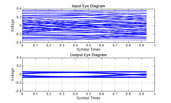
Plot pulse response comparison, waveform comparison, input, and output eye diagrams.
figure
plot(t,pulseIn,t,pulseOut)
legend('Input','Output')
title('Pulse Response Comparison')
xlabel('Symbol Times'),ylabel('Voltage')
grid on
axis([47 60 -0.1 0.4])
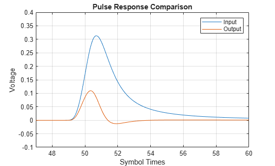
figure
plot(t2,waveIn,t2,waveOut)
legend('Input','Output')
title('Waveform Comparison')
xlabel('Symbol Times'),ylabel('Voltage')
grid on
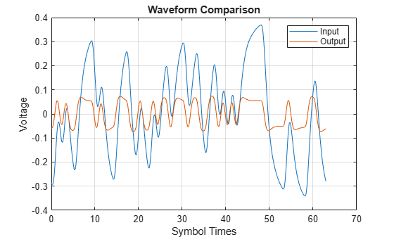
figure
subplot(211),plot(teye,eyeIn,'b')
ax = axis;
xlabel('Symbol Times'),ylabel('Voltage')
grid on
title('Input Eye Diagram')
subplot(212),plot(teye,eyeOut,'b')
axis(ax);
xlabel('Symbol Times'),ylabel('Voltage')
grid on
title('Output Eye Diagram')
This example shows how to process impulse response of a channel one sample at a time using serdes.CTLE System object™.
Use a symbol time of 100 ps and 16 samples per symbol. The channel has 16 dB loss. The peaking frequency is 11 GHz. Select 12-th order pseudorandom binary sequence (PRBS), and simulate the first 500 symbols.
SymbolTime = 100e-12;
SamplesPerSymbol = 16;
dbloss = 16;
DCGain = 0:-1:-26;
PeakingGain = 0:26;
PeakingFrequency = 11e9;
ConfigSelect = 15;
prbsOrder = 12;
M = 500;
Calculate the sample interval.
dt = SymbolTime/SamplesPerSymbol;
Create the CTLE object. Since we are processing the channel one sample at a time, the input waveform is 'sample' type. The object adaptively applies the optimum filter transfer function for the best eye height opening.
CTLE = serdes.CTLE('SymbolTime',SymbolTime,'SampleInterval',dt,...
    'Mode',2,'WaveType','Sample',...
    'DCGain',DCGain,'PeakingGain',PeakingGain,...
    'PeakingFrequency',PeakingFrequency,...
    'ConfigSelect',ConfigSelect);
Create the channel impulse response.
channel = serdes.ChannelLoss('Loss',dbloss,'dt',dt,...
    'TargetFrequency',1/SymbolTime/2);
Initialize PRBS generator.
[dataBit,prbsSeed] = prbs(prbsOrder,1);
Loop through one symbol at a time.
inSymbol = zeros(SamplesPerSymbol,1);
  outWave = zeros(SamplesPerSymbol*M,1);
  for ii = 1:M
      % Get new symbol
      [dataBit,prbsSeed] = prbs(prbsOrder,1,prbsSeed);
      inSymbol(1:SamplesPerSymbol) = dataBit-0.5;

      % Convolve input waveform with channel
      y = channel(inSymbol);

      % Process one sample at a time through the CTLE
      for jj = 1:SamplesPerSymbol
          outWave((ii-1)*SamplesPerSymbol+jj) = CTLE(y(jj));
      end
  end
After truncating the first 75 symbols to allow equalization, use the function reshape on the array of symbols to create the eye diagram.
foldedEye = reshape(outWave(75*SamplesPerSymbol+1:M*SamplesPerSymbol),SamplesPerSymbol,[]);
t = dt*(0:SamplesPerSymbol-1);
figure,plot(t,foldedEye,'b');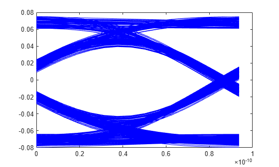
Copyright 2019 The MathWorks, Inc.
Create a GPZ matrix from a uniform number of poles and zeros.
G = [-3;-4;-5;-6];
P = [-15321428571 -13848214285;...
    -15600000000 -14100000000;...
    -15878571428 -14351785714;...
    -16157142857 -14603571428];
Z = [-5574642857;-4960100000;-4435821428;-3981285714];

gpz1 = serdes.CTLE.GainPoleZeroToGPZ(G,P,Z);
Create a second GPZ matrix from a varying number of poles.
G = [0;-1;-2];
P = {[-23771428571,-13092857142];...
    [-17603571428,-13344642857];...
    [-17935714285,-13596428571,-15321428571]};
Z = {-10492857142;-7914982142;-6845464285};
gpz2 = serdes.CTLE.GainPoleZeroToGPZ(G,P,Z);
Combine the two matrices into a 3D GPZ matrix.
gpz = serdes.CTLE.CombineSlices(gpz1,gpz2)
gpz =
gpz(:,:,1) =

   1.0e+10 *

   -0.0000   -1.5321   -0.5575   -1.3848         0         0
   -0.0000   -1.5600   -0.4960   -1.4100         0         0
   -0.0000   -1.5879   -0.4436   -1.4352         0         0
   -0.0000   -1.6157   -0.3981   -1.4604         0         0


gpz(:,:,2) =

   1.0e+10 *

         0   -2.3771   -1.0493   -1.3093         0         0
   -0.0000   -1.7604   -0.7915   -1.3345         0         0
   -0.0000   -1.7936   -0.6845   -1.3596         0   -1.5321
         0         0         0         0         0         0
Create a CTLE from the 3D GPZ matrix.
CTLE3D = serdes.CTLE('Specification','GPZ Matrix','GPZ',gpz,'FilterMethod','Cascaded')
CTLE3D =
  serdes.CTLE with properties:

   Main
             Mode: 2
    Specification: 'GPZ Matrix'
              GPZ: [4×6×2 double]
      SliceSelect: 0
     ConfigSelect: 0

  Show all properties
Extended Capabilities
Version History
Introduced in R2019aSee Also
CTLE | GainPoleZeroToGPZ | CombineSlices | SaturatingAmplifier | serdes.SaturatingAmplifier | AGC | serdes.AGC | DFECDR | serdes.DFECDR | optPulseMetric