Main Content

gearMeshFaultBands

Construct frequency bands around the characteristic fault frequencies of meshing gears for spectral feature extraction

Since R2019b

Description

example

FB = gearMeshFaultBands(FR,Ni,No) generates characteristic fault frequency bands FB of gear mesh using the rotational speed of the input gear FR and the number of teeth on the input Ni and output gear No respectively. The values in FB have the same implicit units as FR

example

FB = gearMeshFaultBands(___,Name,Value) allows you to specify additional parameters using one or more name-value pair arguments.

example

[FB,info] = gearMeshFaultBands(___) also returns the structure info containing information about the generated fault frequency bands FB.

example

gearMeshFaultBands(___) with no output arguments plots a bar chart of the generated fault frequency bands FB.

Examples

collapse all

For this example, consider a simple gear set with an 8-toothed pinion on the input shaft meshing with a 42-toothed spur gear on the output shaft. Assume that the input shaft is spinning at 20 rpm. Construct the gear mesh frequency bands using the physical characteristics of the gear set.

Ni = 8;
No = 42;
FR = 20;
[FB,info] = gearMeshFaultBands(FR,Ni,No)
FB = 5×2

   19.0000   21.0000
    2.8095    4.8095
   79.0000   81.0000
  159.0000  161.0000
  159.0000  161.0000

info = struct with fields:
        Centers: [20 3.8095 80 160 160]
    FaultGroups: [1 2 3 4 5]
         Labels: {'1Fi'  '1Fo'  '1Fa'  '1Fm'  '1Fm'}

FB is a 5x2 array which includes the primary frequencies 1Fi, 1Fo, 1Fa and 1Fm respectively. The structure info contains the center frequencies and labels of each frequency range in FB.

For this example, consider a simple gear set with an 8-toothed pinion on the input shaft meshing with a 42-toothed spur gear on the output shaft. Assume that the input shaft is driven at 20 Hz. The dataset motorSignal.mat contains vibration data for the gear mesh sampled at 1500 Hz.

First, construct the gear mesh frequency bands using the physical characteristics of the gear set. Construct the frequency bands with the first 3 sidebands.

Ni = 8;
No = 42;
FR = 20;
FB = gearMeshFaultBands(FR,Ni,No,'Sidebands',1:3)
FB = 15×2

   19.0000   21.0000
    2.8095    4.8095
   79.0000   81.0000
   99.0000  101.0000
  119.0000  121.0000
  139.0000  141.0000
  179.0000  181.0000
  199.0000  201.0000
  219.0000  221.0000
  147.5714  149.5714
      ⋮

FB is a 15x2 array which includes the primary frequencies and their sidebands.

Load the vibration data and compute PSD and frequency grid using pspectrum. Use a frequency resolution of 0.5.

load('motorSignal.mat','C');
fs = 1500;
[psd,freqGrid] = pspectrum(C,fs,'FrequencyResolution',0.5);

Now, use the frequency bands and PSD data to compute the spectral metrics.

spectralMetrics = faultBandMetrics(psd,freqGrid,FB)
spectralMetrics=1×46 table
    PeakAmplitude1    PeakFrequency1    BandPower1    PeakAmplitude2    PeakFrequency2    BandPower2    PeakAmplitude3    PeakFrequency3    BandPower3    PeakAmplitude4    PeakFrequency4    BandPower4    PeakAmplitude5    PeakFrequency5    BandPower5    PeakAmplitude6    PeakFrequency6    BandPower6    PeakAmplitude7    PeakFrequency7    BandPower7    PeakAmplitude8    PeakFrequency8    BandPower8    PeakAmplitude9    PeakFrequency9    BandPower9    PeakAmplitude10    PeakFrequency10    BandPower10    PeakAmplitude11    PeakFrequency11    BandPower11    PeakAmplitude12    PeakFrequency12    BandPower12    PeakAmplitude13    PeakFrequency13    BandPower13    PeakAmplitude14    PeakFrequency14    BandPower14    PeakAmplitude15    PeakFrequency15    BandPower15    TotalBandPower
    ______________    ______________    __________    ______________    ______________    __________    ______________    ______________    __________    ______________    ______________    __________    ______________    ______________    __________    ______________    ______________    __________    ______________    ______________    __________    ______________    ______________    __________    ______________    ______________    __________    _______________    _______________    ___________    _______________    _______________    ___________    _______________    _______________    ___________    _______________    _______________    ___________    _______________    _______________    ___________    _______________    _______________    ___________    ______________

      0.0054125             19          0.0051216        0.55167             4.25          0.41848        0.0022699             81          0.0029792       0.0012756           99.438        0.0019134       0.0023457           119.25        0.0032812       0.0030216           139.75        0.0036398       0.0015424           180.06        0.0021249       0.0023163           200.81        0.0029269        0.013511            221           0.012079        0.0037697           148.06          0.003914         0.0020528           151.56          0.0025637        0.0021721            156.5          0.0022927        0.0020822           162.81          0.0015729        0.0015305           168.25          0.001575         0.0010234           170.44          0.0013135        0.46577    

spectralMetrics is a 1x46 table with peak amplitude, peak frequency and band power calculated for each frequency range in FB. The last column in spectralMetrics is the total band power, computed across all 15 frequencies in FB.

For this example, consider a simple pinion and gear set with an input shaft speed of 1800 rpm. Considering that the pinion on the input shaft has 6 teeth and the gear on the output shaft has 8 teeth, visualize the frequency bands for the gear mesh.

FR = 1800;
Ni = 6;
No = 8;
gearMeshFaultBands(FR,Ni,No)

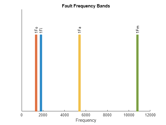
From the plot, observe the following:

  • Output shaft defect frequency, 1Fo at 1350 Hz

  • Input shaft defect frequency, 1Fi at 1800 Hz

  • Assembly phase defect frequency, 1Fa at 5400 Hz

  • Gear mesh defect frequency, 1Fm at 10800 Hz

Input Arguments

collapse all

Rotational speed of the input gear, specified as a positive scalar. FR is the fundamental frequency around which gearMeshFaultBands generates the fault frequency bands. Specify FR either in Hertz or revolutions per minute.

Number of teeth on the input gear, specified as a positive integer.

Number of teeth on the output gear, specified as a positive integer.

Name-Value Arguments

Specify optional pairs of arguments as Name1=Value1,...,NameN=ValueN, where Name is the argument name and Value is the corresponding value. Name-value arguments must appear after other arguments, but the order of the pairs does not matter.

Before R2021a, use commas to separate each name and value, and enclose Name in quotes.

Example: ...,'Harmonics',[1,3,5]

Harmonics of the fundamental frequency to be included, specified as the comma-separated pair consisting of 'Harmonics' and a vector of positive integers. The default value is 1. Specify 'Harmonics' when you want to construct the frequency bands with more harmonics of the fundamental frequency.

Sidebands around the fundamental frequency and its harmonics to be included, specified as the comma-separated pair consisting of 'Sidebands' and a vector of nonnegative integers. The default value is 0. Specify 'Sidebands' when you want to construct the frequency bands with sidebands around the fundamental frequency and its harmonics.

Width of the frequency bands centered at the nominal fault frequencies, specified as the comma-separated pair consisting of 'Width' and a positive scalar. The default value is 10 percent of the fundamental frequency. Avoid specifying 'Width' with a large value so that the fault bands do not overlap.

Units of the fault band frequencies, specified as the comma-separated pair consisting of 'Domain' and either 'frequency' or 'order'. Select:

  • 'frequency' if you want FB to be returned in the same units as FR.

  • 'order' if you want FB to be returned as number of rotations relative to FR.

Logical value specifying whether negative nominal fault frequencies have to be folded about the frequency origin, specified as the comma-separated pair consisting of 'Folding' and either true or false. If you set 'Folding' to true, then faultBands folds the negative nominal fault frequencies about the frequency origin by taking their absolute values such that the folded fault bands always fall in the positive frequency intervals. The folded fault bands are computed as [max(0, |F|W2), |F|+W2], where W is the 'Width' name-value pair and F is one of the nominal fault frequencies.

Output Arguments

collapse all

Fault frequency bands, returned as an Nx2 array, where N is the number of fault frequencies. FB is returned in the same units as FR, in either Hertz or orders. Use the generated fault frequency bands to extract spectral metrics using faultBandMetrics. The generated fault bands, [FW2, F+W2], are centered at the characteristic defect frequencies and their harmonics and sidebands for:

  • Input shaft defect frequency, Fi

  • Output shaft defect frequency, Fo

  • Gear mesh defect frequency, Fm

  • Assembly phase pass defect frequency, Fa

When you specify the sidebands, gearMeshFaultBands computes the sidebands with respect to the input and output shaft defect frequencies:

  • Fault frequency bands for input gear defects with its harmonics and the first sideband at Fi

  • Fault frequency bands for output gear defects with its harmonics and the first sideband at Fo

gearMeshFaultBands truncates negative fault frequency bands automatically and generates a warning message.

The value W is the width of the frequency bands, which you can specify using the 'Width' name-value pair.

Information about the fault frequency bands in FB, returned as a structure with the following fields:

  • Centers — Center fault frequencies

  • Labels — Labels describing each frequency

  • FaultGroups — Fault group numbers equal to the number of frequencies

Algorithms

gearMeshFaultBands computes the different characteristic fault frequencies as follows:

  • Input shaft defect frequency, Fi=FR

  • Output shaft defect frequency, Fo=NiNoFR

  • Gear mesh defect frequency, Fm=NiFR=NoFo

  • Assembly phase pass defect frequency,Fa=Fmgcd(Ni,No)

References

[1] Lang, George Fox. “S&V geometry 101.” Sound and Vibration 33 (1999): 16-26.

Version History

Introduced in R2019b