Estimate PMSM Parameters Using Custom Hardware
This example includes an algorithm to determine the parameters of a permanent magnet synchronous motor (PMSM) using any custom motor-control hardware (hardware not used in the Motor Control Blockset™ examples). The algorithm determines these parameters:
Phase resistance,
 (Ohm)
(Ohm)
daxis inductance, (Henry)
qaxis inductance, (Henry)
Back-EMF constant,
 (Vpk_LL/krpm, where Vpk_LL is the peak voltage line-to-line measurement)
Motor inertia,
 (Kg.m^2)
Friction constant,
 (N.m.s)
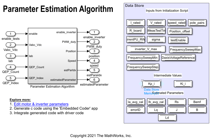
The algorithm accepts the minimum required inputs and runs tests on the target hardware to estimate the PMSM parameters.
The example needs a quadrature encoder sensor to measure the rotor position and provide real-time rotor position feedback. This workflow helps you to integrate the parameter estimation algorithm with the drivers for your motor-control hardware. It supports any three-phase PMSM.
The workflow includes these four steps to prepare, deploy, and run the PMSM parameter estimation algorithm on your hardware:
1. Generate code for the parameter estimation algorithm using Embedded Coder®
2. Obtain C code for the custom hardware drivers
3. Integrate parameter estimation algorithm code with the driver code
4. Deploy the integrated code to hardware
Note: This workflow does not support simulation. You can use any motor-control hardware to run this example.
Prerequisites
Ensure that the PMSM has a quadrature encoder sensor and calibrate the sensor.
The parameter estimation algorithm needs the motor position as detected by a quadrature encoder position sensor. To detect the motor position correctly by using the sensor, calibrate the quadrature encoder that is attached to the motor under test. For instructions, see Quadrature Encoder Offset Calibration.
Calibrate the offset values of the ADC (or current sensor) peripheral available in your hardware. For instructions, see Open-Loop Control and ADC Offset Calibration.
Ensure that the PMSM is in no-load condition.
Custom Hardware Configuration
Controller hardware
Inverter hardware
A PMSM with a quadrature encoder sensor
DC power supply
Required MathWorks Products
To build the parameter estimation algorithm included in this example, you need these products:
Motor Control Blockset
Fixed-Point Designer™
Embedded Coder®
Open MATLAB Project and Prepare Parameter Estimation Model
Use one of these methods to open the MATLAB® project:
Click Open Project.
Use the following command to access the supporting files of the example and open the MATLAB project.
openExample('mcb/EstimatePMSMParametersUsingCustomHardwareExample');
The MATLAB project opens and shows the following files:
parameter_estimation_algorithm.slx(model containing the parameter estimation algorithm)
parameter_estimation_init.m(model initialization script for the parameter estimation algorithm)
Note:
Verify and update the motor, inverter, and other parameters related to the target hardware and parameter estimation algorithm in the model initialization script
parameter_estimation_init.m.
The rated speed of the motor (variable
motorParam.ratedSpeed) must be less than 25000 RPM.
The tests protect the hardware from over-current faults. However, to ensure that these faults do not occur, keep the rated current of the motor (variable
motorParam.nomCurrent) less than the maximum current supported by the inverter.
If you have an SMPS-based DC power supply unit, set a safe current limit on the power supply for safety reasons.
Generate Code For Parameter Estimation Algorithm Using Embedded Coder
1. After you open the MATLAB project, double-click the parameter_estimation_algorithm.slx model.
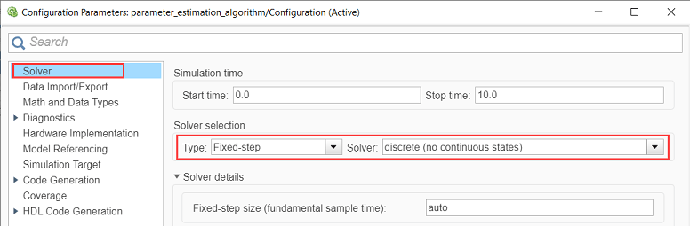
2. Select Modeling > Model Settings > Model Settings to open the Configuration Parameters dialog box.
3. In the Solver Selection area of the Solver tab, update the Type and Solver fields.
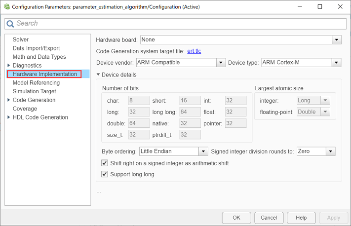
4. In the Hardware Implementation tab of the Configuration Parameters dialog box, configure the parameters according to your hardware.
5. Update the hardware setup parameters (including the quadrature encoder and ADC offsets) in the model initialization script (parameter_estimation_init.m).
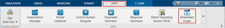
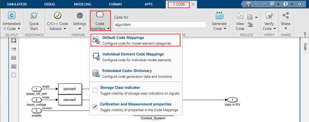
6. In the Simulink toolstrip of the model, select Apps > Embedded Coder to open the Embedded Coder application.
7. In the Simulink toolstrip, select C Code > Code Interface > Default Code Mappings to open the Code Mappings - C dialog box.
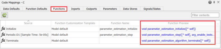
8. In the Code Mappings - C dialog box, open the Functions tab.
9. For a listed C function, click the hyperlink under the Function Preview column to open the Configure C Initialize Function Interface dialog box.
10. Use the Configure C Initialize Function Interface dialog box to configure the interface and arguments of the C function.
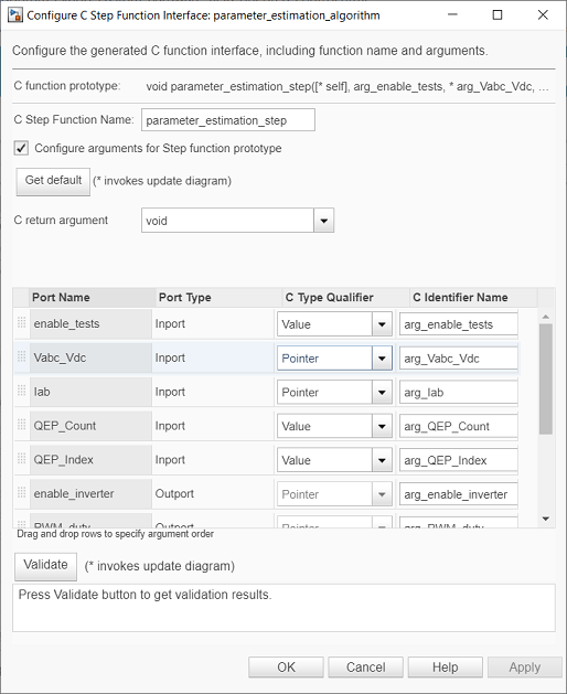
11. Click Apply and OK to complete configuring the C function.
12. Repeat steps 9 to 11 for all the listed functions.
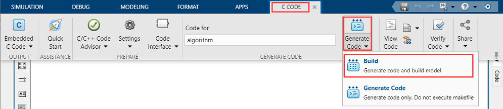
13. In the Simulink toolstrip of the target model, select C Code > Generate Code > Build to build the model and generate a .c file for the target model for the current controller.
This image shows an example of a C function available in the generated current controller code.

Note: The generated C function uses the interface that you configured in step 10.
Obtain C Code for Custom Hardware Drivers
You can use the code generation software supported by the hardware manufacturer to configure the hardware peripherals and generate C code for the hardware drivers.
Alternatively, you can also use a manually written driver code.
Integrate Parameter Estimation Algorithm Code with Driver Code
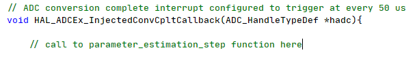
1. Call the parameter estimation algorithm functions from the driver code using the configured function parameters. This image shows a call to a parameter estimation algorithm C function.
2. Use the return value from the function call to complete integrating the driver with the parameter estimation algorithm.
This figure describes the program control flow of the example.
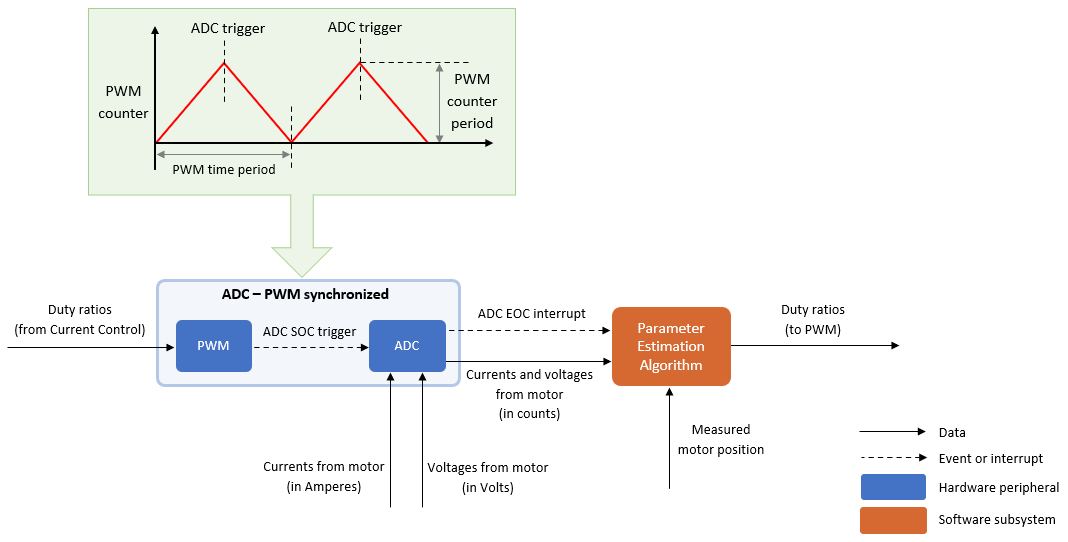
For other details about the recommended code structure (that is used by the Motor Control Blockset examples), see Program Control Flow of Motor Control Blockset Examples.
Deploy Integrated Code to Hardware
1. Complete the hardware connections.
2. Use the code generation and deployment software supported by the hardware manufacturer to compile, build, and generate a binary (for example .HEX) file from the integrated code. Use the software to flash the binary file to the target hardware.
3. The integrated code running on the target hardware saves the computed motor parameters in these global variables:
Rs— Phase resistance
Ld—daxis inductance
Lq—qaxis inductance
Bemf— Back-EMF constant
J— Motor inertia
B— Friction constant
See Also
Apps
Blocks
- PMSM Rs Estimator | Ld Estimator | Lq Estimator | PMSM Mechanical Parameter Estimator | PMSM Parameter Estimation Configurator | ACIM Parameter Estimation Configurator | Id0 Estimator | ACIM Rs Estimator | RrL Estimator | ACIM Mechanical Parameter Estimator
Topics
- Estimate Induction Motor Parameters Using Parameter Estimation Blocks
- Estimate PMSM Parameters Using Parameter Estimation Blocks
- Estimate PMSM Parameters Using Parameter Estimation Blocks on Real-Time Systems
- Estimate PMSM Parameters Using FPGA-Based Motor Control Development Kit
- Run-Time Parameter Estimation of PMSM Using Sensor Feedback
- Generate Motor Control Models for Selected Algorithm and Hardware