Motor Hardware Configurator
Configure and validate motor and control hardware
Since R2024b
Description
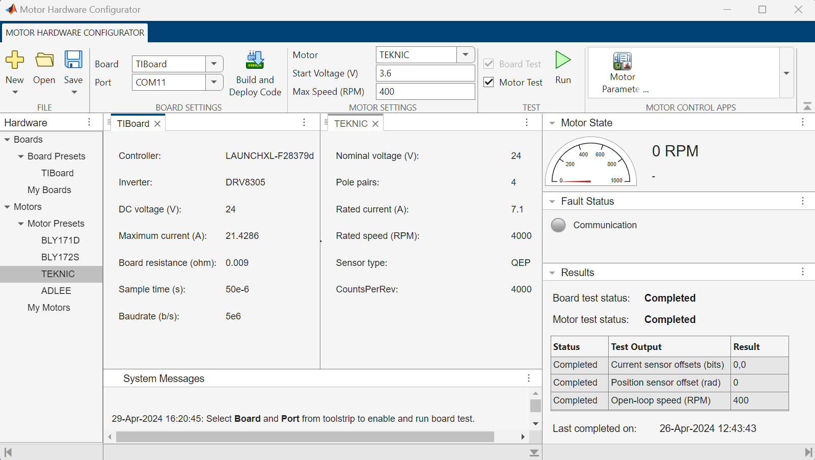
The Motor Hardware Configurator app enables you to interactively configure, test, and validate your motor control hardware. The app runs sanity tests that check and validate the deployed code, hardware connections, as well as serial communication between the hardware and host computer.
The app prepares your hardware to run specific tests, such as the ones needed to estimate the motor parameters. Therefore, running this app is a prerequisite to using the Motor Parameter Estimator app.
Using the Motor Hardware Configurator app, you can:
Use hardware configuration setting presets for (controller and inverter) boards and motors or create your own custom board and motor configuration setting profiles to deploy and run algorithm for the board and motor tests.
Run the board-tests to perform multiple sanity checks on the controller and inverter hardware boards. For example, use these tests to:
Check for compatibility between the deployed code and target hardware.
Detect missing hardware connections.
Validate serial communication between the controller hardware and host computer.
Run the motor-tests to:
Compute the current sensor offsets (in bits).
Compute the position sensor offset (in radians).
Run the motor using open-loop control to reach a steady speed (in RPM).
For details about current sensor (or ADC) offset computation and running the motor using open-loop (V/F) control, see Run 3-Phase AC Motors in Open-Loop Control and Calibrate ADC Offset. For details about computing the quadrature encoder position sensor offset value, see Quadrature Encoder Offset Calibration for PMSM.
Configure or tune the starting voltage (in volts) and maximum speed (in RPM) for the open-loop motor run.
Save and restore board and motor test sessions.
Interactively debug and troubleshoot errors, faults, and test failures.
Launch the Motor Parameter Estimator app such that it can use the board and motor presets or profiles that you validated using the Motor Hardware Configurator app.
Note
The app uses the System Messages panel as well as pop-up dialogs to interactively guide you by providing debugging and troubleshooting instructions, error messages, warnings, and other status updates.
Open the Motor Hardware Configurator App
Simulink® Toolstrip: On the Apps tab, under the Setup to Run on Hardware group, click the Motor Hardware Configurator app icon to launch the app.
Examples
Use Board and Motor Presets to Deploy Test Algorithm
The Motor Hardware Configurator app includes the following hardware configuration setting presets for (controller and inverter) boards as well as motors.
Board Preset
TIBoard— Hardware configuration setting for the LANUCHXL-F28379d controller and DRV8305 inverter.
Motor Presets
BLY171DBLY172STEKNICADLEE
The following procedure shows how to use a board preset to configure and deploy the board and motor test algorithm to the controller.
Complete hardware connections for the LANUCHXL-F28379d controller, DRV8305 inverter, and motor.
Open the Motor Hardware Configurator app.
In the Boards > Board Presets section of the Hardware panel, click the
TIBoardpreset to open the associated configuration settings in the documents panel as shown below.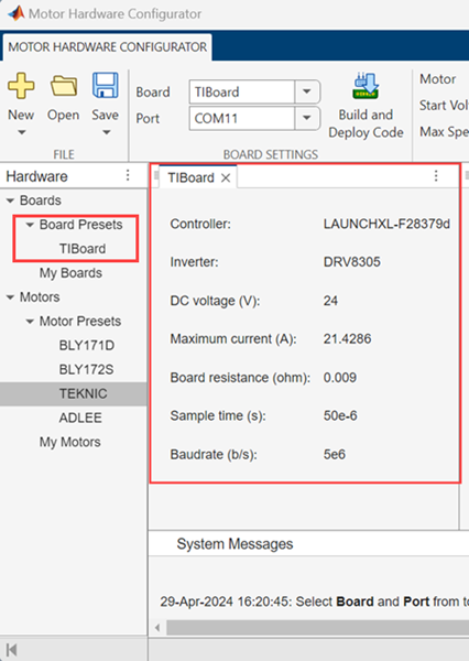
Opening the
TIBoardpreset in the documents panel automatically sets the Board field, available in the Board Settings section of the app toolstrip, toTIBoard.Alternatively, set the Board field to
TIBoarddirectly without opening the preset.Use the Port field, available in the Board Settings section of the app toolstrip, to select a communication port that connects with the hardware.
Click the Build and Deploy Code button in the app toolstrip to deploy the board and motor test algorithm to the controller. The following figure shows the messages that the app displays during the build and deploy process.

The app uses the board preset to configure the board and motor test algorithm before you deploy the algorithm to the controller.
After you deploy the board and motor test algorithm, the app can:
Run board tests for
TIBoard.Run motor tests by sending the motor configuration settings (for a motor preset that you select in the Motor field) to the controller using serial communication, which enables the algorithm to customize the deployed tests for the motor you are using.
You can click a motor preset in the Hardware panel to open it in the documents panel. After viewing the motor presets, you can use one of these methods to select a preset in the Motor field:
Click a motor preset in the Hardware panel.
Switch to a motor preset in the documents panel.
Set the Motor field directly to a motor preset.
You can also create custom configuration setting profiles for your board and motor. After you create these profiles, the fields Board and Motor also show these profiles (in addition to the presets).
Use Custom Board and Motor Profiles to Deploy Test Algorithm
The Motor Hardware Configurator app also enables you to create custom configuration setting profiles for your board and motor.
Complete hardware connections for the controller, inverter, and motor that you are using.
Open the Motor Hardware Configurator app.
Follow these steps to create a custom board or motor profile:
Right-click empty space in the Hardware panel, and select New > Board to add a new custom board profile.
Enter a suitable name for the custom board profile in the Enter Board Name dialog box and click OK.
The new board profile appears under the Boards > My Boards section of the Hardware panel.
Use a similar procedure to add a custom motor profile by right-clicking empty space in the Hardware panel and selecting New > Motor.
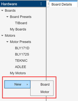
Creating a custom board or motor profile:
Adds the profile under My Boards or My Motors section of the Hardware panel.
Opens the profile in the documents panel.
Sets the Board or Motor field to the newly added custom board or motor profile.
Alternatively, you can right-click a preset or an existing profile and click Duplicate or use the following menus from File section of the app toolstrip to add a custom board or motor profile:
New > Board
New > Motor


In the Boards > My Boards section of the Hardware panel, click a custom board profile to view the associated configuration settings in the documents panel as shown below.
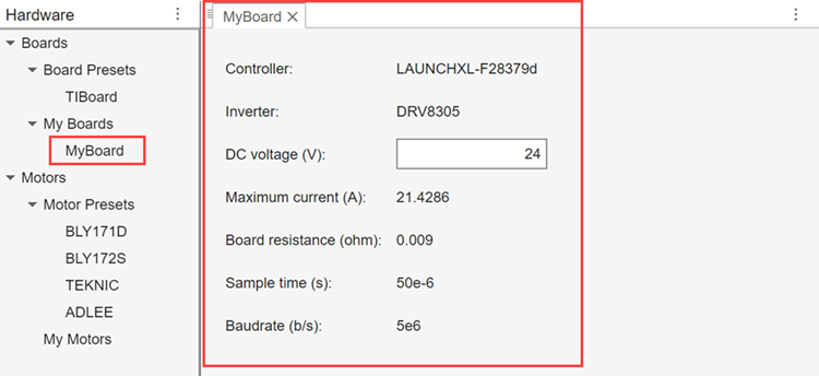
Update the inverter DC voltage supply value in the DC voltage (V) field (if required) and click Save in the app toolstrip to:
Save the field value in the app. This step is required to proceed further.
Launch the Select File to Write window to save the current session data to an existing or a new MAT file. This step is optional.
Opening the custom board profile in the documents panel automatically sets the Board field, available in the Board Settings section of the app toolstrip, to the profile that you opened.
Alternatively, use the Board field to directly select a custom board profile without opening it.
After viewing and updating the custom board profiles, use one of these methods to select a custom board profile that matches the hardware setup you are using:
Click a custom board profile in the Hardware panel.
Switch to a custom board profile in the documents panel.
Set the Board field directly to a custom board profile.
Use the Port field, available in the Board Settings section of the app toolstrip, to select a communication port that connects with the hardware.
Click the Build and Deploy Code button in the app toolstrip to deploy the board and motor test algorithm to the controller. The following figure shows the messages that the app displays during the build and deploy process.

Similar to a preset, the app uses the selected custom board profile to configure the board and motor test algorithm before you deploy the algorithm to the controller.
After you deploy the board and motor test algorithm, the app can:
Run board tests directly for a selected custom board profile.
Run motor tests by sending the motor configuration settings (for a motor profile that you select in the Motor field) to the controller using serial communication, which enables the algorithm to customize the deployed tests for the motor you are using.
You can select a custom motor profile in the Motor field by using instructions similar to those described in step 6.
Run Board Test
The Motor Hardware Configurator app enables you to run only the board tests. After you deploy the board and motor test algorithm to the controller, follow these steps to run the board tests in isolation:
Ensure that you have selected the board and port in the Board and Port fields available in the app toolstrip. Select the Board Test checkbox but clear the Motor Test checkbox.
Click Run to start running the board tests on the hardware.

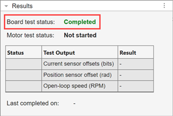
The Board test status field in the Results panel shows the current running status of the board tests.
Run Both Board and Motor Tests
The Motor Hardware Configurator app enables you to run both the board and motor tests together. After you deploy the board and motor test algorithm to the controller, follow these steps to run both the board and motor tests:
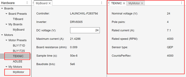
In the Motors section of the Hardware panel, click a motor preset or a custom motor profile (available under My Motors) to view the associated motor configuration settings in the documents panel as shown below.
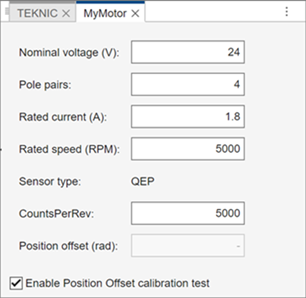
For a custom motor profile, update the following fields (if required):
Nominal voltage (V) — Nominal voltage of the motor (in volts).
Pole pairs — Number of pole pairs available in the motor.
Rated current (A) — Rated current of the motor (in amperes).
Rated speed (RPM) — Rated speed of the motor (in RPM).
CountsPerRev — Counts per revolution or number of counts in one rotation cycle of the quadrature encoder (Counts per revolution = Encoder slits ⨯ Encoder counts per slit).
Position offset (rad) — Position offset of the quadrature encoder sensor (in radians).
Enable position offset calibration test — Select this checkbox to run the tests to compute the position offset for the quadrature encoder sensor. Selecting this checkbox disables the Position offset (rad) field.
Click Save in the app toolstrip to:
Save the preceding fields in the app. This step is required to proceed further.
Launch the Select File to Write window to save the current session data to an existing or a new MAT file. This step is optional.
After viewing the motor presets and profiles as well as updating the custom motor profiles (if required), use one these methods to select a motor preset or custom motor profile that matches the motor you are using, in the Motor field available in the Motor Settings section of the app toolstrip:
Click a motor preset or profile in the Hardware panel.
Switch to a motor preset or profile in the documents panel.
Set the Motor field directly to a motor preset or profile.
Update the following fields, if required:
Start Voltage (V) — The minimum reference voltage (in volts) required to start running the motor using open-loop (or V/F) control.
Max Speed (RPM) — The maximum speed (or frequency) at which the motor can run using open-loop (or V/F) control.
Ensure that you have selected the board and port in the Board and Port fields available in the app toolstrip. Select the Motor Test checkbox.
Note
Selecting the Motor Test checkbox automatically selects the Board Test checkbox.
Click Run to start running both the board and motor tests on the hardware.

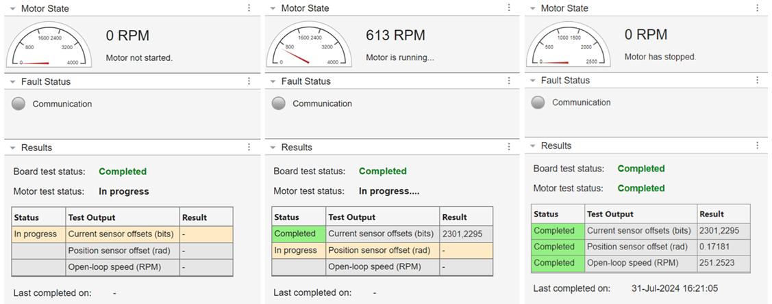
Use the following panels to learn about the test status, faults, and the results:
Motor State — This panel indicates the real-time motor speed when the motor actually runs to determine the following test outputs:
Position sensor offset (rad)
Open-loop speed (RPM)
Fault Status — This panel includes a Communication LED that turns red when the app detects a communication fault.
Results — This panel indicates the current running status of the board and motor tests.
In addition, the panel indicates the Status as well as the Result of the following motor test outcomes:
Current sensor offset (bits) — The ADC offset values computed by the motor tests (in bits).
Position sensor offset (rad) — The quadrature encoder position sensor offset computed by the motor tests (in radians).
Open-loop speed (RPM) — The steady speed (in RPM) achieved by running the motor using open-loop (or V/F) control.
The field Last completed on shows the date and time of the most recent test execution instance when all the tests completed successfully on the hardware.
Save and Restore App Sessions
The Motor Hardware Configurator app enables you to save the data associated with an app session to a MAT file as well as use this file to restore a session.
By default, the app uses a temporary storage to save the current session data. However, this data is lost when you close the app. To avoid such data losses, the app enables you to save the following session information in a MAT file:
App version number.
Board and motor configuration setting presets and profiles.
Most recent status of the Board, Port, Motor, Start Voltage (V), and Max Speed (RPM) fields.
Presets and custom profiles currently open in the documents panel.
Test run status for all presets and custom profiles. In addition, the app saves the following details for each validated board-motor pair (pair of board and motor presets or profiles for which all tests completed successfully):
Information in the Results panel.
Values of Board, Port, Motor, Start Voltage (V), and Max Speed (RPM) for which the tests ran successfully.
Note
The app does not save the preceding data for a board-motor pair, if:
One or more tests do not run to completion.
One or more tests fail.
The app does not save the preceding data, if you only run board tests by selecting the Board Test field. The app saves this data only if you run both board and motor tests by selecting both Board Test and Motor Test fields.
The app deletes the preceding data for a board-motor pair from a session data MAT file, when you save the session after deleting either the associated board, motor, or both of them.
Clicking either Save or Save As options automatically saves the preceding session data in the app temporary storage. However, the following procedure shows how to save this data to a MAT file as well as use the file to restore a saved session:
Anytime while using an unsaved app session, click Save > Save As (or the Save option) to launch the Select File to Write window.
Enter a name for the session data MAT file and save the file to a folder of your choice. You can also replace an existing session data MAT file.
After you save the session data once, you can directly use the Save option to update the session data to the last saved file.
To create a new session, click New > Session from the app toolstrip.
To restore a saved session, click the Open button in the app toolstrip to launch the Select File to Open window. Locate and select the session data MAT file. Click Open to close the previously open session and restore the saved session from the MAT file.
After you restore a session, clicking the Save option updates session data to the same MAT file that you used to restore the session. Use Save As option to save session data to a different file.
Note
If you do not save the previously open session before creating a new session or restoring a saved session, the app discards any unsaved changes available in the previous session. Therefore, it is recommended that you save the current session, before launching a new or a saved session.
Even though, saving the session is not mandatory to use the app, it is recommended that you to save the session regularly to a MAT file to avoid any data losses.
Launch Parameter Estimator App
The Motor Hardware Configurator app enables you to launch the Motor Parameter Estimator app such that it can use one or more pairs of board and motor presets or profiles that you validated.
The specific board and motor tests run by the Motor Hardware Configurator app are necessary to prepare the hardware to run motor parameter estimation algorithms. Therefore, running this app is a prerequisite to using the Motor Parameter Estimator app.
Follow this procedure to launch the Motor Parameter Estimator app:
Ensure that you have validated or successfully completed all the board and motor tests (without any faults, errors, or failures) for the board-motor pair that you want to use with the Motor Parameter Estimator app.
If you had previously ran the board and motor tests successfully, ensure that you restore the data for the associated app session from a MAT file.
In the Motor Control Apps section of the app toolstrip, click the Motor Parameter Estimator icon to launch the Motor Parameter Estimator app.

The Motor Hardware Configurator app transfers the data associated with all the board-motor pairs that you successfully validated in the current app session to Motor Parameter Estimator. The Motor Parameter Estimator app utilizes this data to run motor parameter estimation tests. For more information, see Motor Parameter Estimator.
Related Examples
- Estimate PMSM Parameters Using Custom Hardware
- Estimate Induction Motor Parameters Using Parameter Estimation Blocks
- Estimate PMSM Parameters Using Parameter Estimation Blocks
- Estimate PMSM Parameters Using Parameter Estimation Blocks on Real-Time Systems
- Estimate PMSM Parameters Using FPGA-Based Motor Control Development Kit
- Run-Time Parameter Estimation of PMSM Using Sensor Feedback
- Generate Motor Control Models for Selected Algorithm and Hardware
Version History
Introduced in R2024b
