Verify HDL Module with MATLAB Component Function Using Cosimulation Wizard
This tutorial guides you through the basic steps for setting up an HDL Verifier™ cosimulation between MATLAB® and the HDL simulator, using the Cosimulation Wizard.
The Cosimulation Wizard is a graphical user interface (GUI) that guides you through the process of setting up cosimulation between MATLAB or Simulink® and a hardware description language (HDL) simulator. The supported HDL simulators include Siemens® ModelSim™ and Questa™, and Cadence® Xcelium™.
This tutorial uses MATLAB and ModelSim to verify a register transfer level (RTL) design of a raised cosine filter written in Verilog®. The raised cosine filter is commonly used as a pulse shaping filter in digital communication systems. It produces no inter-symbol interference (ISI) for the input of modulated pulses.
An HDL testbench is provided to generate the stimulus to the raised cosine filter. To verify the correctness of the HDL implementation, the testbench calls a MATLAB callback function that instantiates a reference model of the raised cosine filter. The testbench compares the output of the reference model to that of the HDL implementation.
The Cosimulation Wizard takes the provided Verilog files as its input. It also collects user input required for setting up cosimulation in each step. At the end of the tutorial, the Cosimulation Wizard generates a MATLAB script that compiles the HDL design, a MATLAB script that launches the HDL simulator for cosimulation, and a template for the MATLAB callback function. After modifying the generated template to implement the raised cosine filter, you can verify the correctness of the HDL implementation. Note that Vivado® cosimulation is not supported with MATLAB function.
This tutorial requires ModelSim or Xcelium HDL simulator. This tutorial also assumes that you have read Import HDL Code for MATLAB Function.
The HDL testbench instantiates two raised-cosine filter components: the HDL component and the MATLAB component associated with a MATLAB callback function. The testbench also generates stimulus to both filter components and compares their outputs.
Launch Cosimulation Wizard (MATLAB)
Start MATLAB.
At the MATLAB command prompt, enter
cosimWizardto launch the Cosimulation Wizard.
Configure the Component Function with the Cosimulation Wizard
This tutorial leads you through the following Cosimulation Wizard pages to create an HDL Verifier component function:
Specify Cosimulation Type (MATLAB)
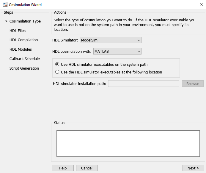
On the Cosimulation Type pane:
Change HDL cosimulation with option set to
MATLAB.If you are using ModelSim, leave HDL Simulator option as
ModelSim. If you are using Xcelium, change HDL Simulator option toXcelium.Leave the default option Use HDL simulator executables on the system path option if the HDL simulator executables appear on your system path. If the executables do not appear in the path, specify the HDL simulator path as described in Cosimulation Type—MATLAB Function.
Click Next to proceed to the HDL Files page.
Select HDL Files (MATLAB)
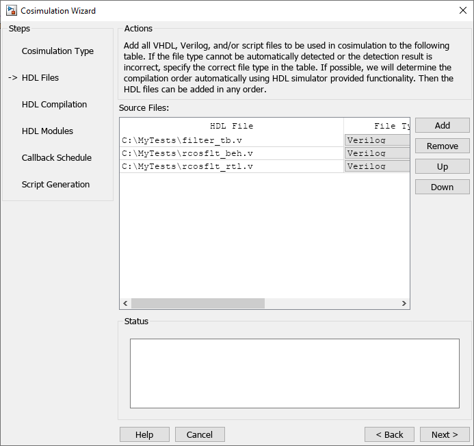
On the HDL Files pane:
Select the Verilog files
filter_tb.v,rcosflt_rtl.v, andrcosflt_beh.v. You can select multiple files in the file browser by holding down theCtrlkey while selecting the files with the mouse.Review the file in the file list with the file type identified as you expected.
Click Next to proceed to the HDL Compilation page.
Specify HDL Compilation Commands (MATLAB)
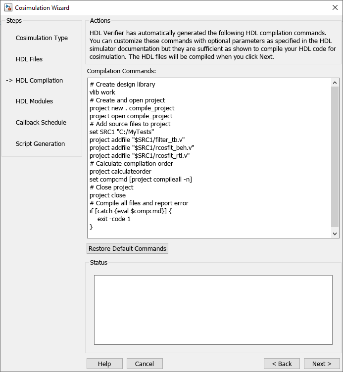
Cosimulation Wizard lists the default commands in the Compilation Commands window. You do not need to change these defaults for this tutorial.
Examine compilation commands.
ModelSim users: Your HDL Compilation pane looks similar to the following:
Xcelium users: Your HDL compilation commands looks similar to the following:
SRC1="C:/MyTests"
xmvlog -64bit "$SRC1/filter_tb.v" "$SRC1/rcosflt_beh.v" "$SRC1/rcosflt_rtl.v"
2. Click Next to proceed to the HDL Modules pane. The MATLAB console displays the compilation log. If an error occurs during compilation, that error appears in the Status area. Change whatever settings you can to remove the error before proceeding to the next step.
Select HDL Modules for Cosimulation (MATLAB)
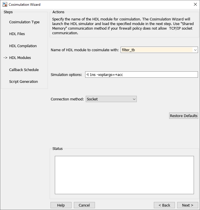
On the HDL Modules pane:
Specify the name of the HDL module/entity for cosimulation. At Name of HDL module to cosimulate with, select
filter_tbfrom the drop-down list to specify the Verilog module you will use for cosimulation. If you do not seefilter_tbin the drop-down list, you can enter it manually.For Connection method, select
Shared Memoryif your firewall policy does not allow TCP/IP socket communication.Click Next to proceed to the Callback Schedule page.
Cosimulation Wizard launches the HDL simulator in the background console using the specified HDL module and simulation options. After the wizard launches the HDL simulator, the Callback Schedule page appears. On Windows® systems, the console remains open. Do not close the console now; close the console when you complete the cosimulation.
Specify Callback Schedule
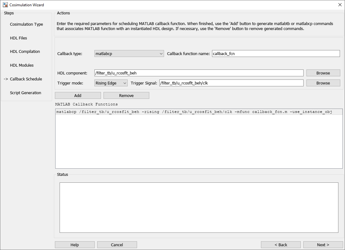
On the Callback Schedule pane:
Leave Callback type as
matlabcp(default). This type instructs the Cosimulation Wizard to create a MATLAB callback function as a component for cosimulation with the HDL simulator.Leave Callback function name as
callback_fcn. The Cosimulation Wizard gives this name to the generated MATLAB callback function.For HDL component, click Browse. Click the expander icon next to
filter_tbto expand the selection. Selectu_rcosflt_beh, and click OK. You specified to the Cosimulation Wizard that the HDL simulator associates this component with the MATLAB callback function.Set Trigger mode to
Rising Edge.For Trigger Signal, click Browse. Click the expander icon next to
filter_tbto expand the selection. Selectu_rcosflt_beh. In the ports list on the right, selectclk. Click OK.Click Add. The Cosimulation Wizard generates the corresponding
matlabcpcommand that associates the HDL moduleu_rcosflt_behwith the MATLAB functioncallback_fcn, as shown in the following image:
For more information on the callback parameters, see the reference page for matlabcp.
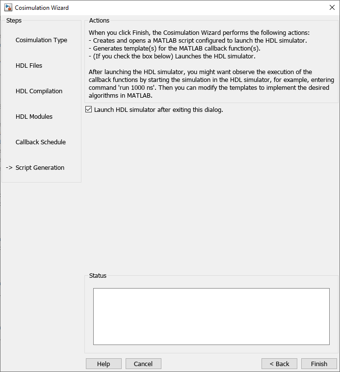
Generate Script
Leave Launch HDL simulator after exiting this dialog selected.
Click Finish to complete the Cosimulation Wizard session and generate scripts.
Customize Callback Function
After you click Finish in the Cosimulation Wizard, the application generates three MATLAB files in the current directory:
compile_hdl_design.m: to recompile the HDL design.launch_hdl_simulator.m: to relaunch the MATLAB server and start the HDL simulator.callback_fcn.m: the MATLAB callback function.
In addition to launching the HDL simulator, HDL Verifier software opens the MATLAB Editor and loads callback_fcn.m (partial image shown).
The generated template comprises four parts:
Initialize internal state(s) of callback function.
Read signal from HDL component.
Write signal to HDL component.
Update internal state(s).
You can modify the template to model a raised cosine filter in MATLAB following the instruction below:
Note: You can find a completed modified callback function in mycallback_solution.m in your current working directory. You can use this file to overwrite the one in your current directory. Name the file "callback_fcn.m", and change the function name to callback_fcn.
Define Internal States
Define two internal states: a 49-element vector to hold filter inputs and a vector of filter coefficients.
Edit callback_fcn.m so that the internal state section contains the following code:
Read Signal from HDL Component
Read the filter input and convert it to a decimal number in MATLAB.
Edit callback_fcn.m so that the read signal section contains the following code:
Write Signal to HDL Component
The input "reset" signal controls the filter output. If reset is low, then the output is the product of the previous inputs and the filter coefficients. MATLAB converts the decimal result to a multivalued logic output for the HDL component.
Edit callback_fcn.m so that the write signal section contains the following code:
Update Internal States
Use the filter input to update the internal 49-element state.
Edit callback_fcn.m so that the update internal states section contains the following code:
Run Cosimulation and Verify HDL Design
Switch to the HDL simulator and enter the following command in the HDL simulator console:
run 200 ns
You see the following output displayed in the HDL simulator:
These messages indicate that the output of the HDL component matches the output of the MATLAB component.