Use HDL Parameters in Cosimulation
You can configure Verilog® parameters or VHDL® generics in a cosimulation. Use the HDLParameterFile property in the cosimulationConfiguration object or the HDL Parameter
File filed in the Cosimulation Wizard to:
Provide your own parameter file, assigning values to known parameters. Use this option when you know the parameters in your design hierarchy and you have specific settings you want to use.
Generate a default parameter file, with parameter values commented out.
Generate a parameter file, and edit it to override default parameter values.
This feature is not supported for Vivado® cosimulation. To manually set parameters for a Vivado cosimulation, see Set HDL Parameters for Vivado Simulation.
Generate and Edit Parameter File
In the Simulation Options pane, specify a filename in the Parameter file field.
Click Generate to create a new parameter file with default parameter values.
Click Edit. In the file that opens, uncomment the lines with the parameters you want to override, and then set their values.
The configuration file includes a line for each HDL parameter, with a default value assigned. Uncomment the line for the parameter you want to configure and assign a value to override the default value.
For example, consider this generated configuration file, generated for ModelSim™ cosimulation.
# Uncomment lines below for any parameter whose default value you want to change.
# For parameters marked "N/A" (not available) the default value could not be
# determined, but you can override in the same way.

#-G/design_top/coeff1=0
#-G/design_top/coeff2=18
#-G/design_top/coeff3=74
To change the value of
coeff1to 32, uncomment that line and assign a value of 32.-G/design_top/coeff1=32 #-G/design_top/coeff2=18 #-G/design_top/coeff3=74Similarly, when you cosimulate with Xcelium™, the parameters in the configuration file are created with the
-gpgdirective to force value assignment for generics and parameters.-gpg "design_top.coeff1=120" #-gpg "design_top.coeff2=18" #-gpg "design_top.coeff3=74"When using VCS®, the file uses
-pvalueto specify Verilog parameters, and-gvaluefor VHDL generics. For example - VCS cosimulation with Verilog:-pvalue /design_top/coeff1=32 -pvalue /design_top/coeff2=18 #-pvalue /design_top/coeff3=74And similarly, VCS cosimulation with VHDL:
-gvalue /design_top/COEFF1=64
#-gvalue /design_top/COEFF2=18
#-gvalue /design_top/COEFF3=74
#-gvalue /design_top/COEFF4=(N/A)
Some values cannot be determined when generating the parameter file, and they show up as
(N/A). You can override their value the same way and replace it with a desired value.
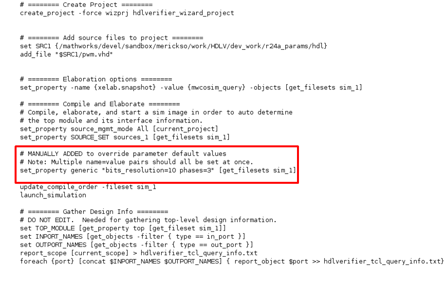
Set HDL Parameters for Vivado Simulation
To set HDL parameters when using Vivado simulator, use the HDLCompilationCommand property in the cosimulationConfiguration object. Alternatively, edit the
Compilation Commands field in the Cosimulation Wizard. For example, edit the default compilation commands
to set values for generics labeled bits_resolution and
phases, highlighted in red:
Note
When setting multiple parameters or generics, they must all be set in a single command.
Supported Data Types for HDL Parameters
Supported Verilog data types
Integer — Up to 32 bit
Real
String — Up to 256 byte
Supported VHDL data types
Integer
Real
String — Up to 256 byte
Time
Bit
Boolean
Enum
std_logic
Cosimulation with Parameterized Port Size
In a Simulink® cosimulation, if your HDL design includes a parameter that configures the width of an input or an output port, the Cosimulation Wizard creates an HDL Cosimulation block with the default value for that port width. To change port width, you can assign a new value to that parameter and re-run the Cosimulation Wizard. If you want override the default value after generating the block, you must follow these steps (not supported for Vivado).
Edit the
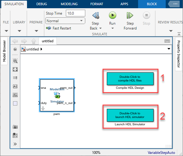
parameter_file and override the parameter value to reflect the desired port width. For example, change theDUT.cfgoutput_widthparameter to8:-G/design_top/output_width=8Make sure that the HDL simulator is not open. In the Simulink canvas that opens after generating the HDL Cosimulation block, double-click the block labeled Compile HDL Design to recompile the HDL design. Then, double-click the block labeled Launch HDL Simulator to start the HDL simulator.
After the HDL simulator opens and loads the design, open the HDL Cosimulation block mask. On the Ports tab, select each port and click Delete until the table is empty.
Click Auto Fill and, in the Auto Fill pane that opens, enter the path to the DUT.
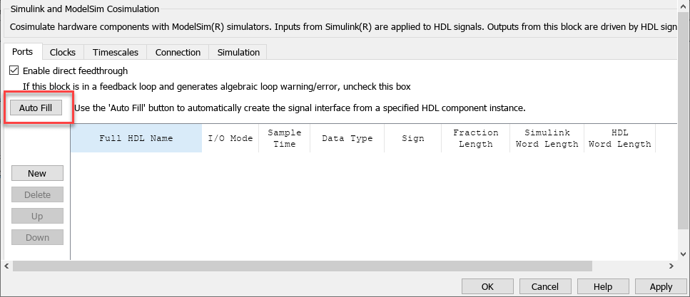
Click Fill. The port list reflects the new parameter value.
This port list includes the HDL ports with the modified port widths, as well as ports for clock and reset. Since Simulink has an implicit clock and reset, you can select and remove those two ports from the list.
Continue cosimulation activities. Do not regenerate the block.