HDL QAM Transmitter and Receiver
This example shows how to use Simulink® blocks that support HDL code generation to implement a 64-QAM transmitter and receiver for HDL code generation and hardware implementation.
The HDL QAM Tx subsystem generates a complex valued, 64-QAM modulated constellation. A floating-point channel model, Channel, is used to add attenuation, channel noise, carrier frequency offset, and fractional delay in order to demonstrate the operation of the receiver subsystem. The HDL QAM Rx subsystem implements a practical digital receiver to mitigate the channel impairments using coarse frequency recovery, timing recovery, frame synchronization, and magnitude and phase recovery. The Text Message Decoding subsystem then receives the data packets, decodes the packets, and prints them to the MATLAB® Command Window.
Structure of the Example
To open the model, enter:
modelname = 'commqamtxrxhdl';
open_system(modelname);
set_param(modelname,'Open','on');
This image shows the top-level structure of the QAM receiver model. The QAM Tx HDL and QAM Rx HDL subsystems are optimized for HDL code generation.

To open the QAM Tx HDL subsystem, enter:
set_param(modelname,'Open','off');
set_param([modelname '/QAM Tx HDL'],'Open','on');
This image shows the detailed structure of the QAM Tx HDL subsystem.

The QAM Tx HDL subsystem contains these components, which are described in more detail in the HDL QAM Transmitter section.
Data Generation & Packetization - Generates the packets to be transmitted, grouping the bits for mapping to symbols
Symbol Mapping - Maps the bits output from the Data Generation & Packetization subsystem to QAM symbols
Pulse Shaping - Performs pulse shaping and upsampling of the symbols using an interpolating RRC (Root Raised Cosine) filter prior to transmission
set_param([modelname '/QAM Tx HDL'],'Open','off');
set_param([modelname '/Channel'],'Open','on');
The structure of the Channel subsystem can be seen below. As the Channel subsystem is intended to be a rough approximation of a AWGN channel with attenuation and frequency offset it is intended to be run in software. As a result blocks which are not supported for HDL code generation can be used here, such as the Phase/Frequency Offset block. The Phase/Frequency Offset block does not support fixed point data types, hence the conversion to double at the input of the Channel subsystem. The signal is converted back to fixed point before being output from the Channel subsystem. A fractional delay and AWGN are applied to the transmitted signal and the Gain block attenuates the signal.

set_param([modelname '/Channel'],'Open','off');
set_param([modelname '/QAM Rx HDL'],'Open','on');
This image shows the detailed structure of the QAM Rx HDL subsystem.
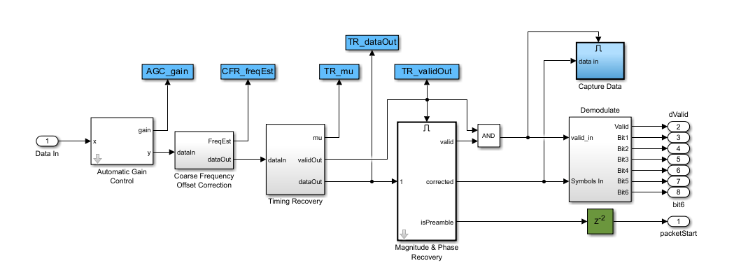
The QAM Rx HDL subsystem contains these components:
Automatic Gain Control - Normalizes the received signal power.
Coarse Frequency Offset Correction - Estimates the approximate frequency offset and corrects. The subsystem also contains the Root Raised Cosine Receive Filter block which downsamples by two.
Timing Recovery - Resamples the input signal according to a recovered timing strobe so that symbol decisions are made at the optimum sampling instants.
Magnitude & Phase Recovery - Performs packet detection, fine-grained phase and amplitude correction.
Demodulate - Demodulates the signal and demaps symbols to bits.
set_param([modelname '/QAM Rx HDL'],'Open','off');
set_param([modelname '/Text Message Decoding'],'Open','on');
This image shows the structure of the Text Message Decoding subsystem.

This subsystem is designed to be run in software, therefore,the subsystem uses frame-based signals to speed up the computation. The Text Message Decoding subsystem has eight sample-based Boolean input signals: dValid, packetStart and signals bit1 to bit6. The dataframer MATLAB Function block converts the sample-based signals to frame-based signals. The demodulated bits are valid only when dValid is set high. The dataframer block uses the dValid signal to fill up a delay line with the received bits and the newPacket signal to forward the data stored in the delay line to the output and reset the delay line.
The Descramble and Print subsystem processes the received data only when its enable signal goes high. This occurs when either the delay line accumulates 336 valid demodulated bits or the newPacket signal is high. This will cause the dataframer block to set the RxGo signal high. While the simulation is running, the Descramble and Print subsystem outputs the string "Hello world! ~64QAM test string~ ###" to the MATLAB Command Window, where '###' is a repeating sequence of '000', '001, '002', ..., '099'. Every 50 packets the subsystem outputs the bit error rate of the data in the last 50 successfully received packets to the MATLAB Command Window.
HDL QAM Transmitter
The HDL QAM Tx contains the Data Generation & Packetization, Symbol Mapping, and Pulse Shaping blocks.
Data Generation & Packetization
The Controller FSM and Data Source subsystems generate the preamble bits, data bits, performs scrambling and builds the packets. Each packet consists of an 84-bit Barker code preamble and 252 bits of scrambled data. The Group Bits block converts the input data bit stream into a six-bit integer at 1/6th of the input sampling rate, as required by the symbol mapper.
The Data Source subsystem has a pipeline delay of two samples. In addition, there is a pipeline delay between the data source and the bit pairing subsystem. The valid signal is therefore delayed to match the pipeline delay of the data path. The Group Bits subsystem reduces the sample rate by a factor of six. Placing a downsample by six in the valid control path ensures that the sample rate matches that of the signal path.
set_param([modelname '/Text Message Decoding'],'Open','off');
set_param([modelname '/QAM Tx HDL/Data Generation & Packetization'],'Open','on');
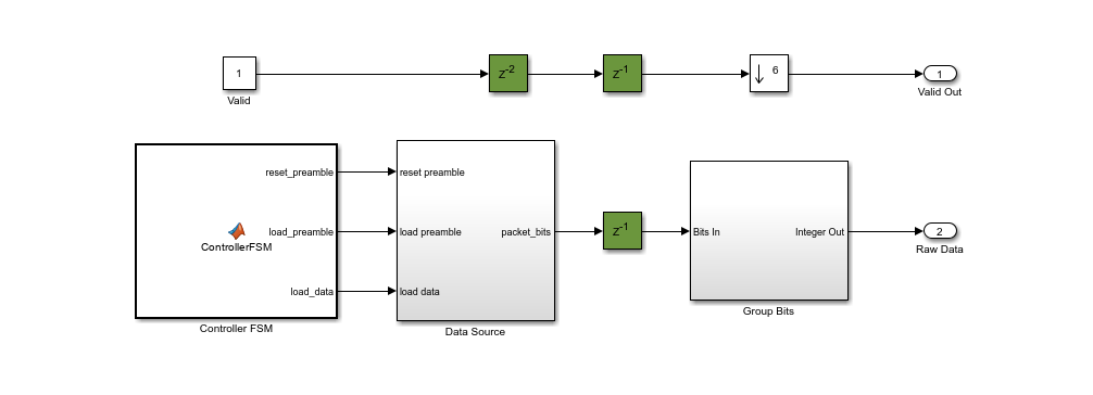
Controller FSM - The Controller FSM block is a MATLAB Function block that implements a control state machine. The FSM has two states, Pack_Preamble and Append_Data. The Pack_Preamble state asserts the load_preamble signal and de-asserts the reset_preamble and the load_data signals. The FSM remains in this state for 84 clock cycles. Then the FSM moves into the Append_Data state, asserts the load_data signal and the reset_preamble signal while releasing the load_preamble signal. The FSM remains in this state for 252 clock cycles. The load_preamble and reset_preamble are Boolean and are used to control the Preamble Address Counter which manages the load of the preamble at the start of each packet. The load_data signal is Boolean and enables the Data Address Counter which controls the loading of data into the packet.
Data Source - The Data Source subsystem contains two lookup tables ( LUTs), storing the preamble and data bits. The Preamble Address Counter subsystem, which is controlled by the reset_preamble and load_preamble signals generated by the Controller FSM block, addresses the preamble lookup LUT.The Data Access Counter, which is enabled by the load_data signal generated by the Controller FSM block, addresses the data lookup LUT. The Preamble Address Counter subsystem has a reset signal, generated by the Controller FSM block, as the same preamble is inserted at the start of each packet. The Data Address Counter subsystem does not have a reset signal as the data address sequence is much longer and varies for each packet as different data bits are placed within each packet. In addition to enabling the counter for the data LUT, the load data input controls when the HDL Data Scrambler component enables selection of preamble or data bits via the Preamble Data Mux block.
set_param([modelname '/QAM Tx HDL/Data Generation & Packetization'],'Open','off');
set_param([modelname '/QAM Tx HDL/Data Generation & Packetization/Data Source'],'Open','on');

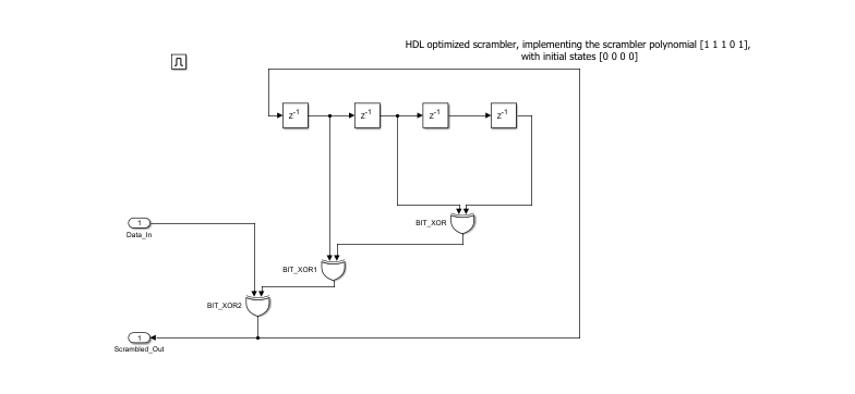
HDL Data Scrambler - To view the HDL Data Scrambler block, enter:
set_param([modelname '/QAM Tx HDL/Data Generation & Packetization/Data Source'],'Open','off');
set_param([modelname '/QAM Tx HDL/Data Generation & Packetization/Data Source/HDL Data Scrambler'],'Open','on');
This image shows the HDL Data Scrambler subsystem. The subsystem uses XOR gates (for modulo 2 addition) and registers. The enabled subsystem ensures that the scrambler is only enabled when there is new input data to be processed.
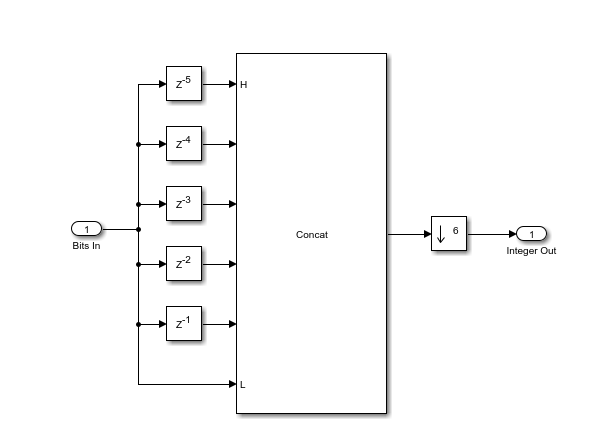
Group Bits - The Group Bits subsystem groups six individual bits into a six-bit unsigned integer output which is the format expected by the symbol mapping component. The delays are used to align six bits at the input of the Bit Concat block, which concatenates into a six-bit unsigned output. This output is then downsampled to select the correct grouping of bits.
set_param([modelname '/QAM Tx HDL/Data Generation & Packetization/Data Source/HDL Data Scrambler'],'Open','off');
set_param([modelname '/QAM Tx HDL/Data Generation & Packetization/Group Bits'],'Open','on');
Symbol Mapping
The Symbol Mapping subsystem uses the Rectangular QAM Modulator Baseband block to map the integer input value onto the appropriate 64-QAM complex valued symbol. The block uses a Gray mapping scheme.
set_param([modelname '/QAM Tx HDL/Data Generation & Packetization/Group Bits'],'Open','off');
set_param([modelname '/QAM Tx HDL/Symbol Mapping'],'Open','on');

Pulse Shaping
The Pulse Shaping subsystem uses the RRC Interpolation Filter block with an upsampling factor of four. A matched filter is implemented in the receiver. The filter is pipelined.
set_param([modelname '/QAM Tx HDL/Symbol Mapping'],'Open','off');
set_param([modelname '/QAM Tx HDL/Pulse Shaping'],'Open','on');

HDL QAM Receiver
The HDL QAM Rx contains the Automatic Gain Control, Coarse Frequency Offset Correction, Timing Recovery, Magnitude & Phase Recovery, and Demodulate blocks.
Automatic Gain Control
The Automatic Gain Control subsystem ensures that the amplitude of the input of the Coarse Frequency Compensation is normalized to the range 1 to -1.
set_param([modelname '/QAM Tx HDL/Pulse Shaping'],'Open','off');
set_param([modelname '/QAM Rx HDL/Automatic Gain Control'],'Open','on');
This image shows the Automatic Gain Control subsystem structure with pipeline registers in green throughout the model.

Coarse Frequency Offset Correction
The Coarse Frequency Offset Correction subsystem estimates and corrects for the frequency offset by using the Luise-Reggiannini algorithm [1]. The Frequency Offset Estimation subsystem makes an estimate based on the output of the Root Raised Cosine Receive Filter block, then frequency offset correction based on this estimate is applied at the input to the Root Raised Cosine Receive Filter. This ensures that the desired portion of the received signal bandwidth is better aligned with the receiver filter frequency response, which improves the SNR compared to correcting at the output of the Root Raised Cosine Receive Filter block.
Because the estimation and correction algorithm is operating in a closed loop, and makes iterative updates to the previous estimates of the frequency offset, the system gradually converges towards a result. The Loop Gain averages the estimates. This architecture is described in [1]. The Root Raised Cosine Receive Filter block implements a downsampling operation so it is necessary to upsample the feedback signal, using the repeat block, to match the rate at the input to the filter.
Note that there is a residual frequency offset at the output of the Coarse Frequency Offset Correction subsystem that varies over time, even if the frequency offset at the input to the subsystem remains the same as the Coarse Frequency Offset Correction subsystem makes new estimates. The Magnitude and Phase Recovery subsystem makes fine-grained correction of the residual offset.
set_param([modelname '/QAM Rx HDL/Automatic Gain Control'],'Open','off');
set_param([modelname '/QAM Rx HDL/Coarse Frequency Offset Correction'],'Open','on');
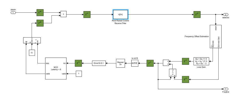
Frequency Offset Estimation: The Frequency Offset Estimation subsystem implements the Luise-Regiannini algorithm, described in [1]. The subsystem raises the signal to the power four to implement a fourth power phase estimator as described in [2]. Two cascaded product blocks, with pipelining added to improve hardware performance implement the estimator. The Discrete FIR Filter implements the filter with rectangular weights, made up of all ones, described in [1]. The FIR Scale scales the FIR output to account for the filter gain. The Complex To Magnitude-Angle HDL Optimized block is used to implement the function, as required by the Luise-Reggiannini algorithm. This block computes the phase using the hardware friendly CORDIC algorithm. For more information, see the Complex to Magnitude-Angle (DSP HDL Toolbox) block. Before the Frequency Offset Estimation subsystem output, the signal is scaled as required by the Luise-Regiannini algorithm and, in addition, is scaled to match the word length of the NCO.
set_param([modelname '/QAM Rx HDL/Coarse Frequency Offset Correction'],'Open','off');
set_param([modelname '/QAM Rx HDL/Coarse Frequency Offset Correction/Frequency Offset Estimation'],'Open','on');

Timing Recovery
To open the Timing Recovery subsystem, enter:.
set_param([modelname '/QAM Rx HDL/Coarse Frequency Offset Correction/Frequency Offset Estimation'],'Open','off');
set_param([modelname '/QAM Rx HDL/Timing Recovery'],'Open','on');
This image shows the Timing Recovery subsystem.
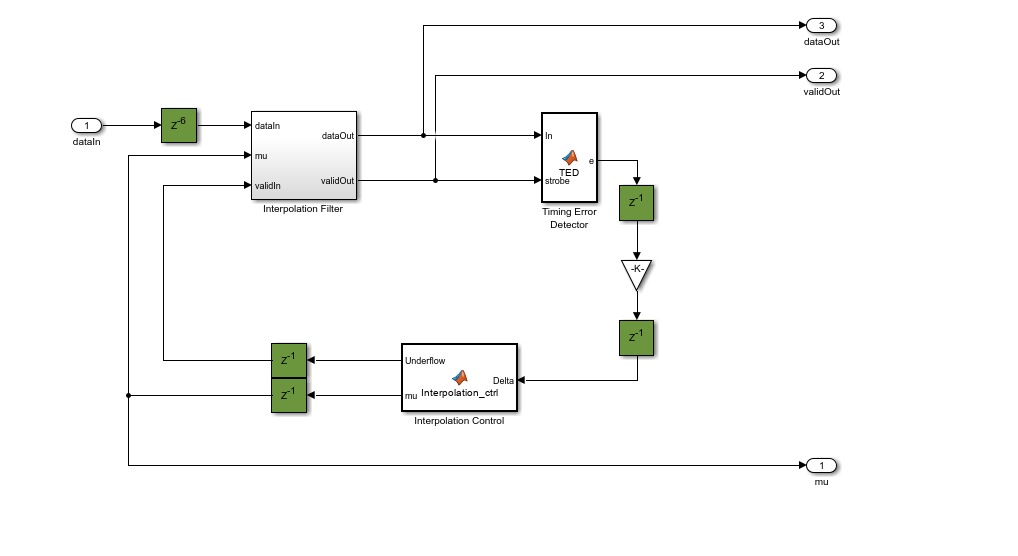
The Timing Recovery subsystem implements a PLL, described in Chapter 8 of [3], to correct the timing error in the received signal. On average, the Timing Recovery subsystem generates one output sample for every two input samples.
The Interpolation Control block implements a decrementing modulo-1 counter, described in Chapter 8.4.3 of [3], to generate the control signal to facilitate the selection of the interpolants of the Interpolation Filter. This control signal also enables the Timing Error Detector (TED), so that it calculates the timing errors at the correct timing instants. The Interpolation Control subsystem updates the timing difference, mu, for the Interpolation Filter, generating interpolants at optimum sampling instants.
The Interpolation Filter is a Farrow parabolic filter with as described in Chapter 8.4.2 of [3]. The filter uses an of 0.5 so that all the filter coefficients become 1, -1/2 and 3/2, which significantly simplifies the interpolator structure. Based on the interpolants the Timing Error Detector, generates timing errors during a zero crossing as described in Chapter 8.4.1 of [3].
The Interpolation Filter introduces a fractional delay to the signal in order to compensate for the timing error. The fractional delay is controlled by the mu input signal. When the timing error (delay) reaches symbol boundaries, there is one extra or missing interpolant in the output. The Timing Error Detector implements bit stuffing or skipping to handle the extra or missing interpolants.
Refer to Chapter 8.4.4 of [3] for details of bit stuffing and skipping. The timing recovery loop normally generates one output symbol for every two input samples. It also outputs a timing strobe (validOut signal) that runs at the input sample rate. Under normal circumstances, the strobe value is simply a sequence of alternating ones and zeros. However, this occurs only when the relative delay between transmitter and receiver contains some fractional part of one symbol period and the integer part of the delay (in symbols) remains constant. If the integer part of the relative delay changes, the strobe value can have two consecutive zeros or two consecutive ones.
Magnitude & Phase Recovery
The Magnitude & Phase Recovery subsystem performs packet synchronization, fine grained frequency recovery and fine grained amplitude recovery.
set_param([modelname '/QAM Rx HDL/Timing Recovery'],'Open','off');
set_param([modelname '/QAM Rx HDL/Magnitude & Phase Recovery'],'Open','on');
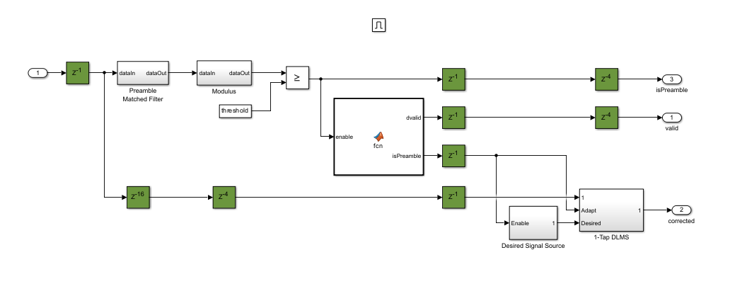
Packet Synchronization: The Preamble Matched Filter subsystem uses the time-reversed complex conjugate of the preamble as the filter weights. The modulus of the output of the Preamble Matched Filter subsystem is calculated using the Modulus subsystem. The output of the Modulus subsystem is then compared to a threshold to detect the preamble at the start of a packet. The MATLAB function block generates a signal, isPreamble, which is held high for the duration of the preamble of each packet. The MATLAB function block also generates the dvalid signal which is set high for the duration of the packet when a preamble has been detected.
Fine Grained Magnitude and Phase Recovery : The 1-Tap DLMS (Delayed Least Mean Squares) filter subsystem, adapting over the preamble and using the reference signal generated by Desired Signal Source, corrects for both phase and magnitude errors. The isPreamble signal, generated by the MATLAB function block and set high for the 14 preamble symbols once a packet has been detected, is used to enable the desired signal source and to enable the Adapt input of the 1-Tap DLMS. When the isPreamble signal is low, the weight in the 1-Tap DLMS is held and the Desired Signal Source is reset. The Delayed LMS (DLMS) [4] algorithm is used here to allow for more pipelining to be introduced and, therefore, reduce the critical path in the filter and increase the maximum clock rate achievable after being implemented in hardware.
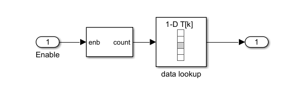
The internal structure of the Desired Signal Source subsystem is shown below. The data lookup LUT contains the preamble symbols.
set_param([modelname '/QAM Rx HDL/Magnitude & Phase Recovery'],'Open','off');
set_param([modelname '/QAM Rx HDL/Magnitude & Phase Recovery/Desired Signal Source'],'Open','on');
The internal structure of the 1-Tap DLMS subsystem is shown below.
set_param([modelname '/QAM Rx HDL/Magnitude & Phase Recovery/Desired Signal Source'],'Open','off');
set_param([modelname '/QAM Rx HDL/Magnitude & Phase Recovery/1-Tap DLMS'],'Open','on');

Demodulate
The Demodulate subsystem maps each 64-QAM input symbol to bits, outputting 6 bits for each input symbol. To generate HDL for the Rectangular QAM Demodulator Baseband block, the minimum distance between symbols must be set to 2. This is 8 times larger than the distance between the symbols generated in the transmitter. As a result, the symbols input to the Demodulate subsystem must be scaled up appropriately. This is done using the Shift Arithmetic block which shifts the binary point left by 3 bits to achieve the required multiplication by 8.
set_param([modelname '/QAM Rx HDL/Magnitude & Phase Recovery/1-Tap DLMS'],'Open','off');
set_param([modelname '/QAM Rx HDL/Demodulate'],'Open','on');

Results and Displays
During the simulation, the model displays successfully received packets in the MATLAB Command Window. At every 50 packets, the MATLAB Command Windows displays the bit error rate of the data in the last 50 successfully received packets.
After running the simulation, the model displays six different figures that illustrate different aspects of the receiver performance. These are shown below, along with an explanation of each plot. The first five plots show the adaption, over the simulation duration, of the Automatic Gain Control, Frequency Offset Estimation, Timing Recovery position estimate, the real part of the constellation at the output of the Timing Recovery subsystem, and at the output of the Magnitude & Phase Recover subsystem. The last plot shows the constellation diagram at the output of Magnitude & Phase Recovery subsystem after any adaption has taken place.
set_param([modelname '/QAM Rx HDL/Demodulate'],'Open','off');
print_cap = evalc('sim(modelname)'); %#ok<NASGU>
clear print_cap;
tscope1.hide;
tscope2.hide;
tscope3.hide;
constDiag1.hide;
constDiag2.hide;
constDiag3.hide;
Automatic Gain Control Plot
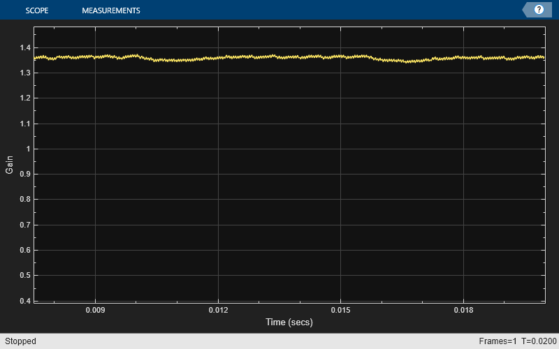
This plot illustrates the Automatic Gain Control subsystem adapting over time to normalize the output. A balance must be struck between how quickly the automatic gain control adapts and how much ripple there is after the gain has reached a relatively constant level. Using a larger automatic gain control loop gain adapts faster, but the amplitude after adaption varies more. Using a smaller loop gain slows the adaption of the automatic gain control, smooths the level after adaption but takes longer to adapt.
tscope1.show;
Frequency Offset Estimate Plot
This plot illustrates how the coarse frequency offset gradually adapts towards the frequency offset introduced by the system, as indicated by the blue horizontal line. This image shows that while the estimate comes close to the actual frequency offset, there is still a residual error that must be addressed later in the system.
tscope1.hide;
tscope2.show;

Timing Recovery Position Plot
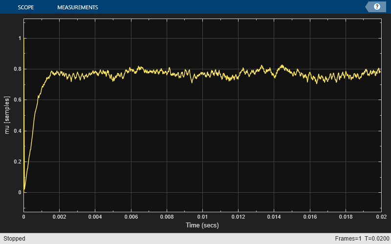
This plot shows the mu input to the Interpolation Filter. Note that mu converges to a steady state, with some ripple over time as the channel delay does not vary during the simulation.
tscope2.hide;
tscope3.show;
Real Part of Timing Recovery Output Plot
This plot illustrates how the real part of the Timing Recovery subsystem output is beginning to converge towards the eight distinct amplitude levels expected for 64QAM. However, as the residual frequency offset remaining after the coarse frequency recovery has not yet been corrected at this point in the receiver, the quality of the signal varies with the distinct amplitude levels more clearly visible at some points than at others. The constellation still has some rotation at this point in the receiver.
tscope3.hide;
constDiag1.show;
Real Part of Symbol Estimates Plot
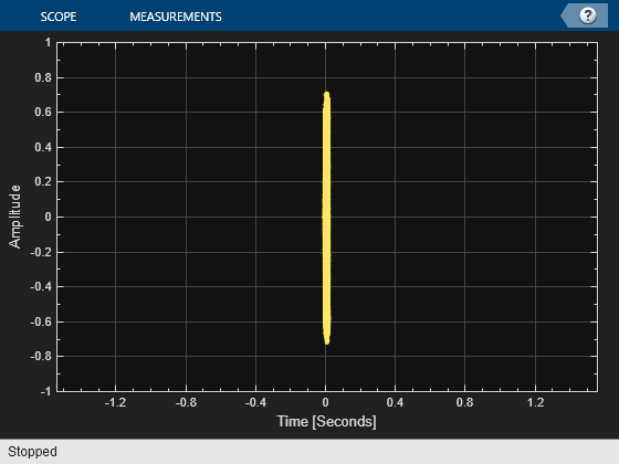
This plot shows how the real part of output of the Magnitude & Phase Recovery subsystem adapts over time. Unlike the previous plot, this diagram is generated after the fine frequency recovery, therefore the constellation should not be rotating. There are no samples initially as the output from the block is not valid, and then eight clear amplitude levels should be seen - representing the eight real amplitude levels of the 64-QAM constellation.
constDiag1.hide;
constDiag2.show;

Recovered Constellation Plot
This plot shows the constellation at the output of the Magnitude & Phase Recovery subsystem after the system has had time to adapt to the channel. Reducing the channel noise should reduce the size of each of the constellation points; increasing the channel noise begins to merge the distinct constellation points together. If the system has not successfully corrected for the frequency offset, then rotation of the constellation is visible here.
constDiag2.hide;
constDiag3.show;

References
1. Luise, M., and R. Reggiannini. “Carrier Frequency Recovery in All-Digital Modems for Burst-Mode Transmissions.” IEEE Transactions on Communications 43, no. 2/3/4 (February 1995): 1169–78. https://doi.org/10.1109/26.380149.
2. Moeneclaey, M., and G. de Jonghe. “ML-Oriented NDA Carrier Synchronization for General Rotationally Symmetric Signal Constellations.” IEEE Transactions on Communications 42, no. 8 (August 1994): 2531–33. https://doi.org/10.1109/26.310611.
3. Rice, Michael. Digital Communications: A Discrete-Time Approach. Upper Saddle River, N.J: Pearson/Prentice Hall, 2009.
4. Long, G., F. Ling, and J.G. Proakis. “The LMS Algorithm with Delayed Coefficient Adaptation.” IEEE Transactions on Acoustics, Speech, and Signal Processing 37, no. 9 (September 1989): 1397–1405. https://doi.org/10.1109/29.31293..
constDiag3.hide;
close_system(modelname);
clear modelname;