Generate IP Core with AXI4-Stream Video Interface
This example shows how to use the AXI4-Stream Video interface to enable high speed video streaming on the generated HDL IP core.
Requirements
To run this example, you must have the following software and hardware installed and set up:
Xilinx® Vivado® Design Suite, with supported version listed in HDL Language Support and Supported Third-Party Tools and Hardware
ZedBoard™
FMC HDMI I/O card (FMC-HDMI-CAM or FMC-IMAGEON)
To set up the Zedboard, refer to the Set up Zynq hardware and tools section in the example Get Started with IP Core Generation from Simulink Model.
Introduction
This example shows how to:
Model a video streaming algorithm using the streaming pixel protocol.
Generate an HDL IP core with AXI4-Stream Video interface.
Integrate the generated IP core into a ZedBoard video reference design with access to HDMI interfaces.
Use the ARM® processor to tune the parameters on the FPGA fabric to change the live video output.
Create your own custom video reference design.

The picture above is a high level architecture diagram that shows how the generated HDL DUT IP core works in a pre-defined video reference design. In this diagram, the HDL DUT IP block is the IP core that is generated from the IP core generation workflow. The rest of the diagram represents the pre-defined video reference design, which contains other IPs to handle the HDMI input and output interfaces.
The HDL DUT IP processes a video stream coming from the HDMI input IP, generates an output video stream, and sends it to the HDMI output IP. All of these video streams are transferred in AXI4-Stream Video interface.
The HDL DUT IP can also include an AXI4-Lite interface for parameter tuning. Compared to the AXI4-Lite interface, the AXI4-Stream Video interface transfers data much faster, making it more suitable for the data path of the video algorithm.
Set Up Zynq Hardware and Tools
1. Set up the ZedBoard and the FMC HDMI I/O card as shown in the figure below. To learn more about the ZedBoard hardware setup, refer to the board documentation.

2. Connect the USB UART cable, the Ethernet cable and the power cable as shown in the figure above (marker 1 to 3).
3. Make sure the JP7 to JP11 jumpers are set as shown in the figure above (marker 4), so you can boot Linux from the SD card. JP7: down; JP8: down; JP9: up; JP10: up; JP11: down.
4. Make sure the J18 jumper are set on 2V5 as shown in the figure above (marker 5).
5. Connect HDMI video source to the FMC HDMI I/O card as shown in the figure above (marker 6). The video source must be able to provide 1080p video output, for example, it could be a video camera, smart phone, tablet, or your computer's HDMI output.
6. Connect a monitor to the FMC HDMI I/O card as shown in the figure above (marker 7). The monitor must be able to support 1080p display.
7. If you haven't already, install the HDL Coder™ Support Package for AMD FPGA and SoC Devices. To install the support package, go to the MATLAB® Toolstrip and click Add-Ons > Get Hardware Support Packages.
8. Make sure you are using the SD card image provided by the HDL Coder Support Package for AMD FPGA and SoC Devices. If you need to update your SD card image, see the Hardware Setup section of Install Support for AMD SoC Boards (Embedded Coder).
9. Set up the Zynq® hardware connection by entering the following command in the MATLAB command window:
h = zynq
The zynq function logs in to the hardware via COM port and runs the ifconfig command to obtain the IP address of the board. This function also tests the Ethernet connection.
10. Set up the Xilinx Vivado synthesis tool path using the hdlsetuptoolpath command. Use your own Vivado installation path when you run the command.
hdlsetuptoolpath('ToolName', 'Xilinx Vivado', 'ToolPath', vivadopath)
Model Video Streaming Algorithm Using the Streaming Pixel Protocol
To deploy a simple Sobel edge detection algorithm on Zynq hardware, the first step is to determine which part of the design to be run on FPGA, and which part of the design to be run on the ARM processor. This example implements the edge detector on FPGA and processes the incoming video stream in AXI4-Stream Video protocol. The ARM processor tunes the parameters on FPGA to change the live video output.
In the example model, the DUT subsystem, Sobel_HW, uses an edge detector block to implement the Sobel edge detection algorithm. The video data and control signals are modeled in the video streaming pixel protocol, which is used by all the blocks in Vision HDL Toolbox™. pixelIn and pixelOut are data ports for video streams. ctrlIn and ctrlOut are control ports for video streams. They are modeled using a bus data type (Pixel Control Bus) which contains following signals: hStart, hEnd, vStart, vEnd, valid.
Four input ports, Threshold, Sobel_Enable, Background_Color and Show_Gradient, are control ports to adjust the parameters the Sobel edge detection algorithms. You can use the Slider Gain or Manual Switch block to adjust the input values of these ports. After mapping these ports to AXI4-Lite interface, the ARM processor can control the generated IP core by writing to the generated AXI interface accessible registers.
modelname = 'hdlcoder_sobel_video_stream';
open_system(modelname);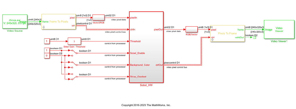
sim(modelname);

Generate HDL IP Core with AXI4-Stream Video Interface
Since R2023b
Next, configure your model for IP core generation, configure your design and target interface, and generate the IP core. This example uses the HDL Code tab in the Simulink® Toolstrip to generate an IP core. To generate an IP core using the HDL Workflow Advisor, see Comparison of IP Core Generation Techniques. The generated IP core can then be deployed to the Zynq hardware and connected to the embedded processor. For a more detailed step-by-step guide, see Get Started with IP Core Generation from Simulink Model. For an overview of how to generate an IP core for a specific hardware platform, see Targeting FPGA & SoC Hardware Overview.
Prepare Model for IP Core Generation
Prepare your model by using the configuration parameters, configure your design by using the IP Core editor, and generate the IP core by using the HDL Code tab of the Simulink Toolstrip. In this example, the target interface settings are already applied to the model. To learn more about saving target interface settings in the model, see Save IP Core Generation and Target Hardware Settings in Model.
In the Apps tab, click HDL Coder. In the HDL Code tab, in the Output section, ensure the drop-down button is set to IP Core.
Select the
Sobel_HWsubsystem, which is the device under test (DUT) for this example. Make sure that Code for is set to this subsystem. To remember the selection, you can click the pin button

Click Settings to open the HDL Code Generation > Target pane of the Configuration Parameters dialog box.
Set the Target Platform parameter to
ZedBoard. If this option does not appear, select Get more to open the Support Package Installer. In the Support Package Installer, select AMD FPGA and SoC Devices and follow the instructions to complete the installation. Ensure the Synthesis Tool is set toXilinx Vivado.Ensure that the Reference Design parameter is set to
Default video system (requires HDMI FMC module).Click OK to save your updated settings.
Configure Design and Target Interface
Configure your design to map to the target hardware by mapping the DUT ports to IP core target hardware and setting DUT-level IP core options. In this example, the AXI4-Stream Video interface communicates in master/slave mode, where the master device sends data to the slave device. Therefore, input data ports are mapped to an AXI4-Stream Video Slave interface, and output data ports are mapped to an AXI4-Stream Video Master interface.
In Simulink, in the HDL Code tab, click Target Interface to open the IP Core editor.
Select the Interface Mapping tab to map each DUT port to one of the IP core target interfaces. If no mapping table appears, click the Reload IP core settings
 button to compile the model and repopulate the DUT ports and their data types.
Map the
pixelIn,ctrlIn,pixelOut, andctrlOutports to the AXI4-Stream video interfaces. Map the control parameter ports, such as theThresholdport, to the AXI4-Lite interface. Ensure the DUT ports are mapped to the interfaces specified in the image below.
Validate your settings by clicking the Validate IP core settings
 button.
In the IP Core editor, you can optionally adjust the DUT-level IP core settings for your target hardware by:
Using the General tab to configure top-level settings, such as the name of the IP core and whether to generate an IP core report.
Using the Clock Settings tab to configure clock-related settings.
Using the Interface Settings tab to configure interface-related settings, such as the register interface and FPGA data capture properties.
Generate IP Core
Next, generate the IP core. In the Simulink Toolstrip, in the HDL Code tab, click Generate IP Core.
Generating an IP core also generates the code generation report. In the Code Generation Report window, in the left pane, click the IP Core Generation Report. The report describes the behavior and contents of the generated custom IP core, such as the register address mapping for the IP core.
Integrate IP into AXI4-Stream Video-Compatible Reference Design
Since R2023b
Next, insert your generated IP core into an embedded system reference design by creating a project, generating an FPGA bitstream, and downloading the bitstream to the Zynq hardware.
The reference design is a predefined Xilinx Vivado project that contains all the elements the Xilinx software needs to deploy your design to the Zynq platform, except for the custom IP core and embedded software. This example uses the HDL Code tab in the Simulink Toolstrip to deploy and verify an IP core. For more information on how to deploy and validate an IP core using the HDL Workflow Advisor, see Comparison of IP Core Deployment and Verification Techniques.
Create IP Core Project
Integrate your generated IP core into the Xilinx platform by creating a Vivado project that organizes and maintains the files associated with the IP core. To create a Vivado project in the Simulink Toolstrip, in the HDL Code tab**, select Build Bitstream >** Create IP Core Project. HDL Coder generates an IP integrator embedded design and displays a link to it in the Diagnostic Viewer.

Click the link in the Simulink Diagnostic Viewer to open the generated Vivado project. In the Vivado tool, click Open Block Design to view the Zynq design diagram, which includes the generated HDL IP core, other video pipelining IPs, and the Zynq processor. As shown in this image, the reference design contains the IPs to handle the:
HDMI input and output interfaces
Color space conversion from YCbCr to RGB
The generated project is a complete Zynq design, including the generated DUT algorithm IP, and the reference design.

Configure Deployment Settings
Next, configure the build bitstream settings. In the Simulink Toolstrip, in the HDL Code tab, select Build Bitstream > Deployment Settings. In the Deployment Settings window, under the Build Bitstream section, select Run build process externally to run the Xilinx synthesis tool in a separate window than the current MATLAB session.

Then, under the Program Target Device section:
Set Programming method to
Downloadto download the FPGA bitstream onto the SD card on your target Zynq board and automatically reload the design when the board power cycles.Set IP Address to your target board IP address.
Set SSH username and SSH Password to your target board settings.

Generate Bitstream and Program Target Device
To generate the bitstream file, in the Simulink Toolstrip, in the HDL Code tab, click Build Bitstream and wait until the synthesis tool runs in the external window.
To download the bitstream, in the HDL Code tab**,** select Build Bitstream > Program Target Device.
Deploy to Processor Using Software Interface Model
To target a portion of your design for the ARM processor, generate a software interface model. The software interface model contains the part of your design that runs in software. It includes all the blocks outside of the HDL subsystem, and replaces the HDL subsystem with AXI driver blocks. If you have an Embedded Coder license, you can automatically generate embedded code from the software interface model, build it, and run the executable on Linux on the ARM processor. The generated embedded software generates AXI driver code from the AXI driver blocks and uses the code to control the HDL Coder generated IP core. You can generate the software interface model at any stage of the IP core generation and IP core integration process.
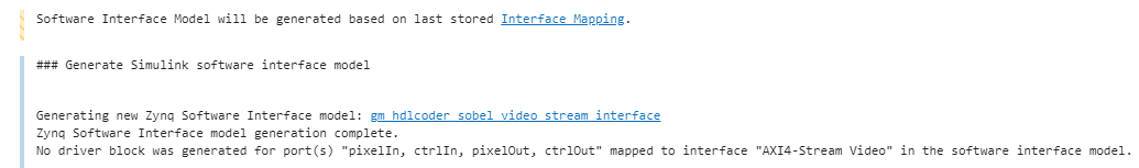
To generate the software interface model, in the Simulink Toolstrip, in the HDL Code tab, select Build Bitstream > Software Interface Model. The Simulink Diagnostic Viewer displays a link to the generated software interface model.
Before you generate code from the software interface model, comment out the Video Source and Video Viewer in the generated model, as shown in this picture. These blocks do not need to run on the ARM processor. Because the ARM processor uses an AXI4-Lite interface to control the FPGA fabric, the actual video source and display interface run on the FPGA fabric. The video source comes from the HDMI input, and the video output is sent to the monitor connected to the HDMI output.

Run Software Interface Model on ZedBoard Hardware
Next, configure the generated software interface model, generate the embedded C code, and run your model on the ARM processor in the Zynq hardware in external mode.
When you prototype and develop an algorithm, it is useful to monitor and tune the algorithm while it runs on hardware. You can use external mode to deploy your algorithm to the ARM processor in the Zynq hardware, and then link the algorithm with the Simulink model on the host computer through an Ethernet connection.
In the generated model, in the Hardware tab, in the Prepare section, click Hardware settings to open the Configuration Parameters dialog box.
In the Run On Hardware section, set Stop time to
inf. Click OK.In the Hardware tab, Run On Hardware section, click Monitor & Tune. Embedded Coder builds the model, downloads the ARM executable to the Zynq hardware, executes it, and connects the model to the executable running on the Zynq hardware.
Use the input switch to the Sobel_Enable port to observe that the live video output switches between the edge detector output and the original video. Use the switch inputs to the Threshold or Background_Color ports to see the different edge detection effects on the live video output. The model sends the parameter values to the Zynq hardware via external mode and the AXI4-Lite interface.
When you are done changing model parameters, click the Stop button in the Simulink Toolstrip, then close the system command window.
Customize the Video Reference Design
Suppose that you want to extend the existing Default video system reference design to add additional pre-processing or post-processing camera pipelining IPs, or that you want to use a different SoC hardware or video camera interface. You can use the Default Video System reference design as a starting point to create your own custom reference design.
For example, the Default video system reference design contains two IP cores that do color space conversion from YCbCr to RGB, as shown in this picture. These two IP cores are generated by HDL Coder when you generate an IP Core. You can generate other pre-processing or post-processing camera pipelining IP cores and add them into a custom reference design to extend your video platform.

For more details on creating your own custom reference design, see the Define Custom Board and Reference Design for AMD Workflow example.