Prepare Model for IP Core Generation
Prepare a model or MATLAB function for IP core generation. The input is a Simulink® model or MATLAB function and a chosen hardware platform. The output is a partitioned model specifically designed for deployment for a standalone FPGA, an FPGA on-board an SoC device, or an FPGA I/O board on Simulink Real-Time™ target machine.
For more details on the workflow, see Targeting FPGA & SoC Hardware Overview.

Topics
- Choose an Interface for an IP Core
Choose an interface to connect your IP core to the rest of your design.
- IP Core Clock Interface
Configure clock inputs for generated IP cores.
- Model Design for AXI4 Register Interface Generation
How to design your model for AXI4 or AXI4-Lite interfaces for scalar, vector ports, bus data types, and read back values.
- IP Core Reset Interface
Learn how HDL Coder™ automatically inserts logic to synchronize global reset signal to IP core clock domain.
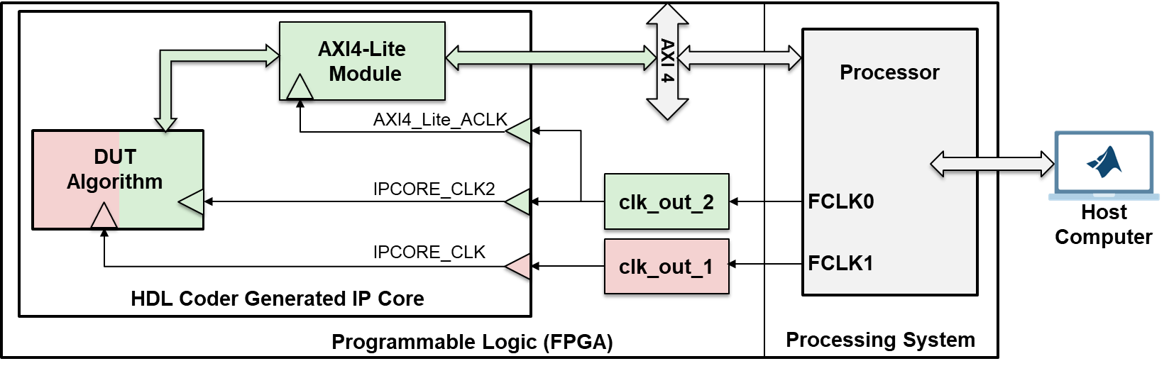
- Enable Clock Domain Crossing on AXI4-Lite Interfaces
Connect different clock signals to IP core DUT and AXI4-Lite interfaces. (Since R2024a)
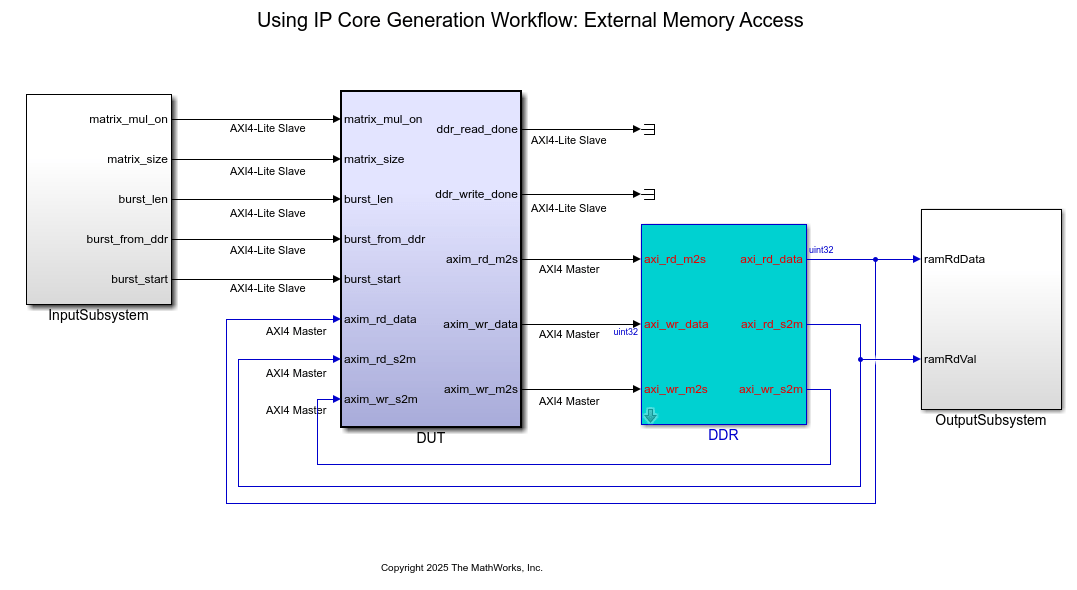
- Map Bus Data Types to a Register Interface
This example shows how to map bus data types to a register interface, generate an HDL IP core with a AXI4 Master interface, perform matrix multiplication in an HDL IP core, and write the output result to DDR memory.
- Model Design for AXI4-Stream Interface Generation
How to design your model for AXI4-Stream vector or scalar interface generation.
- Model Design for AXI4-Stream Video Interface Generation
How to design your model for IP core generation with AXI4-stream video interfaces.
- Model Design for AXI4 Master Interface Generation
Description of AXI4 Master protocol, and how you can design your model for IP core generation with AXI4-Master interfaces.
- Model Design for Frame-Based IP Core Generation
How to design your model to use the frame-to-sample optimization for IP core generation.
- Save IP Core Generation and Target Hardware Settings in Model
This example shows how to save your IP core generation and target hardware settings in a Simulink model.
Featured Examples
Use Clock Domain Crossing to Run DUT Algorithm and AXI4-Lite Interface at Different Frequencies
Use clock domain crossing to run DUT algorithm and AXI4-Lite interface at different clock frequencies.

Generate IP Core with an AXI4-Stream Interface
Use the AXI4-Stream interface to enable high speed data transfer between the processor and FPGA on Zynq® hardware.

Generate IP Core with AXI4-Stream Video Interface
Use the AXI4-Stream Video interface to enable high speed video streaming on the generated HDL IP core.

Perform Large Matrix Operations Using External Memory
Generate an HDL IP core with an AXI4 Master interface, perform matrix multiplication within the IP core, and store the output in external DDR memory.

Generate IP Core with AXI4-Lite Interface
Use the hardware-software co-design workflow to blink LEDs at various frequencies on the Xilinx® Zynq® UltraScale+ MPSoC.

Offload Large Delays from Frame-Based Models to External Memory
Map large delays to external memory when generating an IP core from a frame-based algorithm.

Deploy a Real-Time Video Frame Accumulator by Using External Memory
Build a frame accumulator on Zynq using frame‑to‑sample optimization for real‑time streaming.
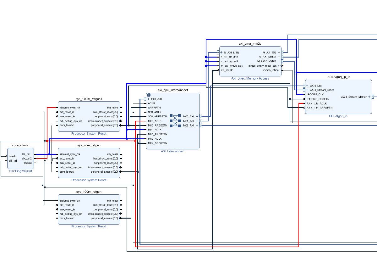
Generate Clock-Domain-Crossing Pulse Synchronizer by Generating a Multiple-Clock IP Core
Generate a multiple-clock IP core and use clock domain crossing logic to transfer data between asynchronous clock domains.
Generate HDL IP Core with AXI4 Master Interface to Access Altera External Memory
Generate an HDL IP core that uses an AXI4 Master interface to interact with Altera® DDR4 external memory on the Intel® Arria® 10 SoC Development Kit. You perform read and write operations on the external memory using MATLAB® as the host.