Hauptinhalt

txsite

Create RF transmitter site

Description

Use a txsite object to create a radio frequency (RF) transmitter site.

A transmitter consists of an RF circuit and an antenna, where the RF circuit excites the antenna with a signal and power. Key characteristics of a transmitter include its output power, operating frequency, and antenna radiation pattern.

Creation

Description

tx = txsite creates a radio frequency transmitter site in geographic coordinates.

example

tx = txsite(coordsys) specifies the coordinate system used to reference the location of the site. By default, transmitter sites use a geographic coordinate system.

tx = txsite(___,PropertyName=Value) sets properties using one or more name-value arguments. This syntax is useful for creating multiple transmitter sites.

  • For geographic transmitter sites, you can specify the location by setting the Latitude, Longitude, and AntennaHeight properties.

  • For Cartesian transmitter sites, you can specify the location by setting the AntennaPosition property.

example

Input Arguments

expand all

Coordinate system used to the reference the location of the site, specified as "geographic" or "cartesian". This argument sets the CoordinateSystem property of the site.

Output Arguments

expand all

Transmitter site, returned as a txsite object or a vector of txsite objects.

Properties

expand all

Site name, specified as one of these options:

  • A string scalar or a character vector. Use this option to create one site or to create multiple sites with the same name.

  • A string vector or a cell array of character vectors. Use this option to create multiple sites and use a different name for each site. The number of names must match the number of sites.

When updating the Name property after creation, if tx is a vector of sites, you must update the property of each site individually by indexing into the vector and specifying a string scalar or a character vector, for example tx(1).Name = "Fenway Park".

Data Types: char | string | cell

Coordinate system used to the reference the location of the site, specified as 'geographic' or 'cartesian'.

  • 'geographic' — Geographic coordinate system. Specify the locations of the transmitter sites using the Latitude, Longitude, and AntennaHeight properties.

  • 'cartesian' — Cartesian coordinate system. Specify the locations of the transmitter sites using the AntennaPosition property.

Data Types: char | string

Latitude coordinates of the site, in degrees, specified as one of these options:

  • A numeric scalar in the range [–90, 90]. Use this option to create one site or to create multiple sites with the same latitude coordinate.

  • A numeric vector with elements in the range [–90, 90]. Use this option to create multiple sites and use a different latitude coordinate for each site. The length of the vector must match the number of sites.

Latitude assumes that the coordinates use the World Geodetic System of 1984 (WGS 84) reference ellipsoid.

When updating the Latitude property after creation, if tx is a vector of sites, you must update the property of each site individually by indexing into the vector and specifying a numeric scalar, for example tx(1).Latitude = 45.098.

Dependencies

To enable this property, the value of CoordinateSystem must be 'geographic'.

Longitude coordinates of the site, in degrees, specified as one of these options:

  • A numeric scalar. Use this option to create one site or to create multiple sites with the same longitude coordinate.

  • A numeric vector. Use this option to create multiple sites and use a different longitude coordinate for each site. The length of the vector must match the number of sites.

Longitude assumes that the coordinates use the WGS 84 reference ellipsoid.

When updating the Longitude property after creation, if tx is a vector of sites, you must update the property of each site individually by indexing into the vector and specifying a numeric scalar, for example tx(1).Longitude = -71.0972.

Dependencies

To enable this property, the value of CoordinateSystem must be 'geographic'.

Antenna element or array, specified as 'isotropic', an antenna object, an array object, a vector of antenna objects, or a vector of array objects. The txsite object supports these antenna options:

  • 'isotropic' which models an antenna that radiates uniformly in all directions.

  • An antenna object from the Antenna Catalog (Antenna Toolbox) or an array object from the Array Catalog (Antenna Toolbox). To specify an antenna object, design the antenna at the required receive frequency by using the design (Antenna Toolbox) function. Then, add the antenna to the transmitter site. This option requires an Antenna Toolbox™ license.

  • An arrayConfig object.

  • An antenna object from Antennas, Microphones, and Sonar Transducers (Phased Array System Toolbox) or an array object from Array Geometries and Analysis (Phased Array System Toolbox). This option requires a Phased Array System Toolbox™ license.

  • A measuredAntenna (Antenna Toolbox) object. The E and EmbeddedE properties of the object must be empty. The Directivity property of the object must be nonempty. This option requires an Antenna Toolbox license. (since R2026a)

Specify a value for Antenna depending on the number of sites you want to create:

  • To create one site or to create multiple sites with the same antenna, specify a scalar antenna or array object.

  • To create multiple sites and use a different antenna for each site, specify a vector of antenna or array objects. The length of the vector must match the number of sites.

When updating the Antenna property after creation, if tx is a vector of sites, you must update the property of each site individually by indexing into the vector and specifying an antenna or array object, for example tx(1).Antenna = arrayConfig(Size=[8 1]).

Antenna x-axis angle with respect to a local Cartesian coordinate system, in degrees, specified as one of these options:

  • A numeric scalar that specifies the azimuth angle. Use this option to create one site or to create multiple sites with the same azimuth angle. When you specify a scalar, the elevation angle is 0.

  • A 2-by-1 numeric vector that specifies the azimuth and elevation angles of the antenna. Use this option to create one site or to create multiple sites with the same azimuth and elevation angles.

  • A 2-by-N numeric matrix that specifies the azimuth and elevation angles of the antenna, where N is the number of sites. Use this option to create multiple sites and use different azimuth and elevation angles for each site.

For sites with geographic coordinates, the azimuth angle is measured counterclockwise from the east along the antenna x-axis. For sites with Cartesian coordinates, the azimuth angle is measured from the global x-axis around the global z-axis. Specify the azimuth angle in the range [–180, 180].

The elevation angle is measured from the antenna x-axis along the horizontal (or xy) plane. Specify the elevation angle in the range [–90, 90].

When updating the AntennaAngle property after creation, if tx is a vector of sites, you must update the property of each site individually by indexing into the vector and specifying a numeric scalar or a 2-by-1 numeric vector, for example tx(1).AntennaAngle = [25 -80].

Antenna height above the ground or building surface, in meters, specified as one of these options:

  • A nonnegative scalar. Use this option to create one site or to create multiple sites with the same antenna height.

  • A vector of nonnegative values. Use this option to create multiple sites and use a different antenna height for each site. The length of the vector must match the number of sites.

Antenna heights must be less than or equal to 6,371,000 m.

When the site coincides with a building, the antenna height measures from the top of the building to the center of the antenna. Otherwise, the height measures from the ground to the center of the antenna.

When updating the AntennaHeight property after creation, if tx is a vector of sites, you must update the property of each site individually by indexing into the vector and specifying a nonnegative scalar, for example tx(1).AntennaHeight = 15.

Dependencies

To enable this property, the value of CoordinateSystem must be 'geographic'.

Data Types: double

Position of the antenna center, in meters, specified as one of these options:

  • A three-element vector that specifies the Cartesian xyz-coordinates of the antenna center. Use this option to create one site or to create multiple sites with the same antenna position.

  • A 3-by-N matrix, where N is the number of sites, and each column specifies the Cartesian xyz-coordinates of the antenna center for that site. Use this option to create multiple sites and use a different antenna position for each site.

When updating the AntennaPosition property after creation, if tx is a vector of sites, you must update the property of each site individually by indexing into the vector and specifying a 3-element vector, for example tx(1).AntennaPosition = [0; 2; 4].

Dependencies

To enable this property, the value of CoordinateSystem must be 'cartesian'.

Data Types: double

System loss, in dB, specified as one of these options:

  • A nonnegative scalar. Use this option to create one site or to create multiple sites with the same system loss.

  • A vector of nonnegative values. Use this option to create multiple sites and use a different system loss for each site. The size of the vector must match the number of sites.

System loss includes transmission line loss and any other miscellaneous system losses.

When updating the SystemLoss property after creation, if tx is a vector of sites, you must update the property of each site individually by indexing into the vector and specifying a nonnegative scalar, for example tx(1).SystemLoss = 10.

Data Types: double

Transmitter operating frequency, in Hz, specified as one of these options:

  • A positive scalar. Use this option to create one site or to create multiple sites with the same operating frequency.

  • A vector of positive values. Use this option to create multiple sites and use a different operating frequency for each site. The size of the vector must match the number of sites.

When the Antenna property contains an antenna element from the Antenna Catalog (Antenna Toolbox) or an array element from the Array Catalog (Antenna Toolbox), the frequency must be in the range [1e3, 200e9].

When you use the transmitter site in a propagation analysis, the frequency must be within the frequency range for the propagation model. For more information about the valid frequency ranges for different propagation models, see Choose a Propagation Model.

When updating the TransmitterFrequency property after creation, if tx is a vector of sites, you must update the property of each site individually by indexing into the vector and specifying a positive scalar, for example tx(1).TransmitterFrequency = 30e9.

Data Types: double

Signal power at transmitter output, in W, specified as one of these options:

  • A positive scalar. Use this option to create one site or to create multiple sites with the same signal power.

  • A vector of positive values. Use this option to create multiple sites and use a different signal power for each site. The size of the vector must match the number of sites.

The transmitter out is connected to the antenna. When Antenna specifies an antenna array, this property specifies the total signal power to the array.

When updating the TransmitterPower property after creation, if tx is a vector of sites, you must update the property of each site individually by indexing into the vector and specifying a positive scalar, for example tx(1).TransmitterPower = 30.

Data Types: double

Object Functions

showShow site in Site Viewer
hideHide site from Site Viewer
distanceDistance between sites
angleAngle between sites
elevationElevation of site
locationCoordinates at distance and angle from site
losDisplay or compute line-of-sight (LOS) visibility status
coverageDisplay or compute coverage map
sinrDisplay or compute signal-to-interference-plus-noise (SINR) ratio
patternDisplay antenna radiation pattern in Site Viewer

Examples

collapse all

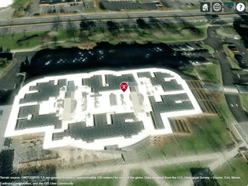
Create a transmitter site. By default, transmitter sites use geographic coordinates. Specify the latitude as 42.3001 degrees and the longitude as -71.3504 degrees.

tx = txsite(Name="MathWorks Apple Hill", ...
    Latitude=42.3001,Longitude=-71.3504);

Display the antenna radiation pattern for the site.

pattern(tx)

Transmitter site and antenna radiation pattern displayed over satellite imagery

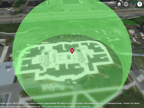
Create a dipole antenna that has a resonant frequency of 2.5e9 Hz. Create a transmitter site in geographic coordinates that uses the dipole antenna.

fq = 2.5e9;
ant = design(dipole,fq);

tx = txsite(Name="MathWorks Apple Hill", ...
    Latitude=42.3001,Longitude=-71.3504, ...
    Antenna=ant,TransmitterFrequency=fq);

Display the transmitter site.

show(tx)

Transmitter site displayed over satellite imagery

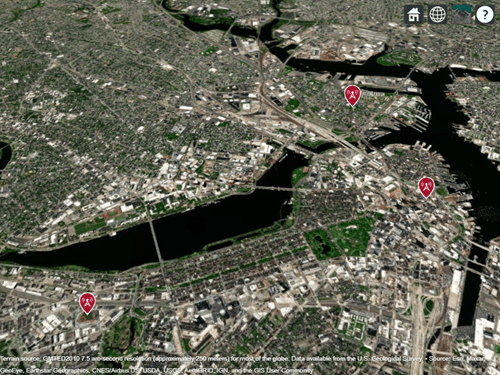
Specify the names, latitudes, and longitudes of three locations.

name = ["Fenway Park","Faneuil Hall","Bunker Hill Monument"];
lat = [42.3467 42.3598 42.3763];
lon = [-71.0972 -71.0545 -71.0611];

Specify the frequency of the transmitters in Hz.

fq = 2.5e9;

Create an array of transmitter sites in geographic coordinates that uses dipole antennas.

txs = txsite(Name=name,Latitude=lat,Longitude=lon, ...
Antenna=dipole,TransmitterFrequency=fq);

Display the transmitter sites.

show(txs)

Three transmitter sites displayed over satellite imagery

Version History

Introduced in R2019b

expand all

See Also

Objects