measuredAntenna
Description
The measuredAntenna object lets you perform port and field
analysis on the measured field data of an antenna or array. You can import measured field data
from a .txt file, .csv file, or .xlsx
file to the MATLAB® workspace and assign it to the relevant
properties of this object. The field data includes Cartesian electric and embedded electric
field components in V/m at the observation points, spherical coordinates of the observation
points, the phase center, number of excitation ports, measurement frequencies, and
S-parameters. The measuredAntenna object also lets you replace the physical
exciter of the curved reflector antennas from the antenna catalog with measured field data of
the exciter and perform fundamental analysis on the reflector antenna using the Physical
Optics solver.
Creation
Description
m = measuredAntenna
m = measuredAntenna(PropertyName=Value)PropertyName is the property
name and Value is the corresponding value. You can specify several
name-value arguments in any order as
PropertyName1=Value1,...,PropertyNameN=ValueN. Properties that you
do not specify, retain their default values.
Properties
Cartesian components of the electric field in V/m at observation points, specified as a P-by-3-by-F matrix. P represents the number of observation points and components are specified in [X Y Z] order. The default value is [0.1 0.1 0.1] V/m at a single observation point. F represents the number of frequencies over which the electric field is measured.
Example:
E(:,:,1) = [0.5 0.3 0.7]
Example: E(1,:,:) = [0.1 0.1 0.1; 0.2 0.3 0.15;...0.5 0.45
0.35]
Data Types: double
Complex Number Support: Yes
Spherical coordinates of the observation points, specified as a P-by-3 matrix. P represents the number of observation points and the coordinates are specified as [Azimuth(degree) Elevation(degree) Radius(meter)]. The default value is a single observation point at [0 90 100].
Example: [30 60 200]
Example: [0 90 100; ...; 359 359 100]
Data Types: double
Cartesian coordinates of the phase center of the measured antenna in meter,
specified as a 1-by-3 vector in [X Y Z] order. The default phase center is at [0 0
0.075]. Phase center is defined as a point in space from which, when emitted, the
far-field phase fronts remain spherical in a certain angular area of interest.
PhaseCenter denotes the average phase center of the incident
electric field, E.
Example: [0 1 1]
Data Types: double
Number of excitation ports in the measured antenna or array, specified as a positive
scalar integer. Number of antenna ports specified in this property must be equal to the
number of antenna ports in EmbeddedE property.
Example: 2
Data Types: double
Frequencies at which the electric field of the antenna or array was measured, specified as a scalar for a single frequency or a F-by-1 vector for multiple frequencies, where F is the number of frequencies.
Example: 1e9
Example: [1e9 1.25e9 1.5e9]
Data Types: double
Coordinate system for the measured field data, specified as a string amongst:
rectangular- Cartesian coordinates, where the points are specified as [x y z].polar- Spherical coordinates, where the points are specified as [azimuth elevation radial].
Example: "polar"
Data Types: string
Azimuth angles used to measure electric field, specified as a scalar or A-by-1 vector in degrees, where A is the number of azimuth angles.
Example: [0:5:90]
Data Types: double
Elevation angles used to measure electric field, specified as a scalar or E-by-1 vector in degrees, where E is the number of elevation angles.
Example: [0:5:90]
Data Types: double
S-parameters for all excitation ports at each frequency, specified as a
sparameters object.
Example: sparameters("sample.s2p")
Example: sparameters(dipole,70e6,50)
Example: sparameters(linearArray,140e6)
Data Types: double
Cartesian components (P-by-3) of embedded electric field
magnitude in V/m when the FieldCoordinate is
"rectangular", for each port (N) at each
frequency (F) at each observation point in the
Direction property, specified as a 4-D array. Number of points is
defined by P.
When the FieldCoordinate is "polar", the
three columns in P-by-3 matrix represent azimuth angle, elevation
angle, and radial magnitude. Set NumPorts value greater than 1 to
enable this property.
Example: Let EmbeddedE = emb in a rectangular coordinate system.
To access the electric field data for a single port at a single frequency, use
emb(:,:,1,1).
Data Types: double
Complex Number Support: Yes
Impedance to terminate other ports except the excitation port while computing the
embedded pattern, specified as a real scalar. Set NumPorts value
greater than 1 to enable this property.
Example: 75
Data Types: double
Excitation amplitude of array elements in Volts, specified as one of these options:
Positive scalar — Use this value to specify uniform amplitude across the individual elements.
Positive vector of size 1-by-NumPorts — Use this value to specify non-uniform amplitude across the individual elements.
The default AmplitudeTaper is 1 Volt.
Example: 2
Example: [2 4]
Data Types: double
Phase shift of array elements in degrees, specified as one of these options:
Numeric scalar — Use this value to specify uniform phase shift across the individual elements.
Numeric vector of size 1-by-NumPorts — Use this value to specify non-uniform phase shift across the individual elements.
The default PhaseShift is zero degrees.
PhaseShift values correspond to the respective excitation voltages
of the individual elements in the array.
Example: 45
Example: [45 -45]
Data Types: double
Option to calculate the total electric field from embedded field data, specified as one of these options:
Numeric or logical
0(false)— Use this value to disable this option.Numeric or logical
1(true)— Use this value to enable this option.
By default, this option is disabled. When this option is enabled, the
EHfields and pattern functions use the
calculated total electric field in their results.
Example: true
Data Types: logical
Object Functions
EHfields | Electric and magnetic fields of antennas or embedded electric and magnetic fields of antenna element in arrays |
pattern | Plot radiation pattern of antenna, array, or embedded element of array |
sparameters | Calculate S-parameters for antenna or array |
Note
When measuredAntenna is an input argument to the above
functions:
The
EHfieldsfunction can be used only to visualize the E-field data contained in theEproperty of themeasuredAntenna.The
patternfunction can have itsTypeargument set to onlyefield.The
sparametersfunction plots the S-parameters when no output argument is specified or creates asparametersobject when an output argument is specified.
Examples
This example shows how to use the measured electric field data of a dipole antenna to excite a parabolic reflector structure. The example uses EHfields function to generate the electric field data. You can import the electric field data of any external antenna into the measuredAntenna object. The electric field magnitude is expressed in V/m and coordinates are expressed in meters and degrees.
Create Dipole antenna, save field data and plot electric field
Design a dipole antenna operating at 10 GHz. Save the complex E-field data of this dipole antenna in a variable.
freq = 10e9;
ant = design(dipole(Tilt=90,TiltAxis=[0 1 0]),freq);
E = EHfields(ant,freq)
E = 3×441 complex

  12.2492 +50.7204i  10.9830 +50.0817i   7.2868 +48.1070i   1.4638 +44.6408i  -5.9963 +39.4936i -14.4447 +32.5478i -23.1139 +23.9147i -31.1701 +14.1574i -37.7710 + 4.5564i -42.1360 - 2.7961i -43.6684 - 5.6012i -42.1360 - 2.7961i -37.7710 + 4.5564i -31.1701 +14.1574i -23.1139 +23.9147i -14.4447 +32.5478i  -5.9963 +39.4936i   1.4638 +44.6408i   7.2868 +48.1070i  10.9830 +50.0817i  12.2492 +50.7204i  12.2492 +50.7204i  11.1051 +50.1436i   7.7649 +48.3712i   2.5080 +45.2950i  -4.2156 +40.7988i -11.8109 +34.8519i -19.5772 +27.6408i -26.7579 +19.7300i -32.6013 +12.2039i -36.4360 + 6.6227i -37.7749 + 4.5369i -36.4360 + 6.6227i -32.6013 +12.2039i -26.7579 +19.7300i -19.5772 +27.6408i -11.8109 +34.8519i  -4.2156 +40.7988i   2.5080 +45.2950i   7.7649 +48.3712i  11.1051 +50.1436i  12.2492 +50.7204i  12.2492 +50.7204i  11.4228 +50.3047i   9.0112 +49.0475i   5.2258 +46.9296i   0.4051 +43.9584i  -5.0085 +40.2214i -10.5012 +35.9467i -15.5309 +31.5501i
   0.0191 + 0.0071i   0.0155 + 0.0116i   0.0115 + 0.0155i   0.0072 + 0.0187i   0.0027 + 0.0210i  -0.0020 + 0.0221i  -0.0065 + 0.0223i  -0.0106 + 0.0218i  -0.0137 + 0.0210i  -0.0158 + 0.0203i  -0.0165 + 0.0201i  -0.0158 + 0.0203i  -0.0137 + 0.0210i  -0.0106 + 0.0218i  -0.0065 + 0.0223i  -0.0020 + 0.0221i   0.0027 + 0.0210i   0.0072 + 0.0187i   0.0115 + 0.0155i   0.0155 + 0.0116i   0.0191 + 0.0071i   0.0191 + 0.0071i  -0.3208 - 0.2160i  -1.3069 - 0.9109i  -2.8600 - 2.1211i  -4.8516 - 3.8972i  -7.1112 - 6.2625i  -9.4357 - 9.1600i -11.6018 -12.3805i -13.3806 -15.4882i -14.5582 -17.8213i -14.9717 -18.6996i -14.5582 -17.8213i -13.3806 -15.4882i -11.6018 -12.3805i  -9.4357 - 9.1600i  -7.1112 - 6.2625i  -4.8516 - 3.8972i  -2.8600 - 2.1211i  -1.3069 - 0.9109i  -0.3208 - 0.2160i   0.0191 + 0.0071i   0.0191 + 0.0071i  -0.5280 - 0.3556i  -2.1176 - 1.4606i  -4.6137 - 3.3253i  -7.7981 - 5.9465i -11.3836 - 9.2543i -15.0340 -13.0573i -18.3899 -16.9940i
   0.0000 + 0.0001i  -7.2267 - 4.8924i -13.8167 - 9.7575i -19.1754 -14.4814i -22.7937 -18.7870i -24.2914 -22.1762i -23.4561 -23.9067i -20.2734 -23.0454i -14.9513 -18.7079i  -7.9486 -10.6411i   0.0000 + 0.0000i   7.9486 +10.6411i  14.9513 +18.7079i  20.2734 +23.0454i  23.4561 +23.9067i  24.2914 +22.1762i  22.7937 +18.7870i  19.1754 +14.4814i  13.8167 + 9.7575i   7.2267 + 4.8924i  -0.0000 - 0.0001i   0.0000 + 0.0001i  -6.8731 - 4.6457i -13.1344 - 9.2239i -18.2136 -13.5889i -21.6250 -17.4521i -23.0095 -20.3392i -22.1726 -21.5919i -19.1151 -20.4533i -14.0568 -16.3107i  -7.4547 - 9.1466i   0.0000 + 0.0000i   7.4547 + 9.1466i  14.0568 +16.3107i  19.1151 +20.4533i  22.1726 +21.5919i  23.0095 +20.3392i  21.6250 +17.4521i  18.2136 +13.5889i  13.1344 + 9.2239i   6.8731 + 4.6457i  -0.0000 - 0.0001i   0.0000 + 0.0001i  -5.8454 - 3.9358i -11.1561 - 7.7223i -15.4375 -11.1610i -18.2748 -13.9710i -19.3715 -15.7815i -18.5823 -16.1686i -15.9384 -14.7525i
Plot the electric field vectors of this dipole antenna.
fig = figure;
EHfields(ant,freq,ViewField="E");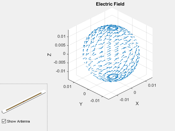
Extract coordinates of electric field points and pass field data to measuredAntenna
Extract the Cartesian coordinates of direction vectors from the electric field plot using quiver. Convert these Cartesian coordinates into spherical coordinates using cart2sph function.
quH = fig.Children(3).Children;
pts = [quH.XData;quH.YData;quH.ZData];
[phi,theta,radius] = cart2sph(pts(1,:),pts(2,:),pts(3,:));
dir = [rad2deg(phi)' 90-rad2deg(theta)' radius'];
Create a measuredAntenna object and pass the electric field data (in V/m.), spherical coordinates of the electric field points, and the phase center of the this field to the respective properties of the measuredAntenna object.
ms = measuredAntenna;
ms.E = E';
ms.Direction = dir;
lambda = 3e8/freq;
f = 5 * lambda;
ms.PhaseCenter = [0 0 f];
ms.FieldFrequency = freq;
Create parabolic reflector antenna with measuredAntenna as exciter
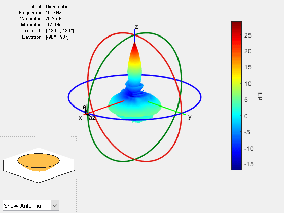
Create a parabolic reflector antenna with the measuredAntenna data as Exciter. Plot the radiation pattern of this antenna at 10 GHz.
back = reflectorParabolic;
back.Exciter = ms;
figure
pattern(back,10e9)
This example shows how to import and analyze the measured pattern data of a linear array.
Import Measured Pattern Data
Define the frequency range of the data and number of antenna elements in the array. Import the data from a text file using readmatrix function.
The text file contains measured field data for a linear array of dipoles at 3 frequencies 1.6GHz, 2GHz, and 2.4GHz.
fRange = [1.6e9 2e9 2.4e9];
numAnt = 2;
patternData = readmatrix("MeasuredData.txt");
patternData
patternData = 2701×30 complex
102 ×
0.0000 - 0.0000i 0.0000 + 0.0000i 0.0000 + 0.0000i -0.0000 + 0.0000i 0.0000 - 0.0000i 0.0000 + 0.0000i -0.0000 - 0.0000i 0.0000 - 0.0000i 0.0000 - 0.0000i -1.8000 + 0.0000i -0.9000 + 0.0000i 0.1500 + 0.0000i 0.0000 - 0.0000i 0.0000 + 0.0000i 0.0000 + 0.0000i -0.0000 + 0.0000i 0.0000 + 0.0000i 0.0000 + 0.0000i -0.0000 - 0.0000i 0.0000 - 0.0000i 0.0000 + 0.0000i 0.0000 + 0.0000i 0.0000 - 0.0000i 0.0000 + 0.0000i -0.0000 - 0.0000i 0.0000 - 0.0000i 0.0000 - 0.0000i 0.0000 + 0.0000i 0.0000 - 0.0000i 0.0000 - 0.0000i
0.0000 - 0.0000i 0.0000 + 0.0000i 0.0000 + 0.0000i -0.0000 + 0.0000i 0.0000 - 0.0000i 0.0000 + 0.0000i -0.0000 - 0.0000i 0.0000 - 0.0000i 0.0000 - 0.0000i -1.7500 + 0.0000i -0.9000 + 0.0000i 0.1500 + 0.0000i 0.0000 - 0.0000i 0.0000 + 0.0000i 0.0000 + 0.0000i -0.0000 + 0.0000i 0.0000 + 0.0000i 0.0000 + 0.0000i -0.0000 - 0.0000i 0.0000 - 0.0000i 0.0000 + 0.0000i 0.0000 + 0.0000i 0.0000 - 0.0000i 0.0000 + 0.0000i -0.0000 - 0.0000i 0.0000 - 0.0000i 0.0000 - 0.0000i 0.0000 + 0.0000i 0.0000 - 0.0000i 0.0000 - 0.0000i
0.0000 - 0.0000i 0.0000 + 0.0000i 0.0000 + 0.0000i -0.0000 + 0.0000i 0.0000 - 0.0000i 0.0000 + 0.0000i -0.0000 - 0.0000i 0.0000 - 0.0000i 0.0000 - 0.0000i -1.7000 + 0.0000i -0.9000 + 0.0000i 0.1500 + 0.0000i 0.0000 - 0.0000i 0.0000 + 0.0000i 0.0000 + 0.0000i -0.0000 + 0.0000i 0.0000 + 0.0000i 0.0000 + 0.0000i -0.0000 - 0.0000i 0.0000 - 0.0000i 0.0000 + 0.0000i 0.0000 + 0.0000i 0.0000 - 0.0000i 0.0000 + 0.0000i -0.0000 - 0.0000i 0.0000 - 0.0000i 0.0000 - 0.0000i 0.0000 + 0.0000i 0.0000 - 0.0000i 0.0000 - 0.0000i
0.0000 - 0.0000i 0.0000 + 0.0000i 0.0000 + 0.0000i -0.0000 + 0.0000i 0.0000 - 0.0000i 0.0000 + 0.0000i -0.0000 - 0.0000i 0.0000 - 0.0000i 0.0000 - 0.0000i -1.6500 + 0.0000i -0.9000 + 0.0000i 0.1500 + 0.0000i 0.0000 - 0.0000i 0.0000 + 0.0000i 0.0000 + 0.0000i -0.0000 + 0.0000i 0.0000 + 0.0000i 0.0000 + 0.0000i -0.0000 - 0.0000i 0.0000 - 0.0000i 0.0000 + 0.0000i 0.0000 + 0.0000i 0.0000 - 0.0000i 0.0000 + 0.0000i -0.0000 - 0.0000i 0.0000 - 0.0000i 0.0000 - 0.0000i 0.0000 + 0.0000i 0.0000 - 0.0000i 0.0000 - 0.0000i
0.0000 - 0.0000i 0.0000 + 0.0000i 0.0000 + 0.0000i -0.0000 + 0.0000i 0.0000 - 0.0000i 0.0000 + 0.0000i -0.0000 - 0.0000i 0.0000 - 0.0000i 0.0000 - 0.0000i -1.6000 + 0.0000i -0.9000 + 0.0000i 0.1500 + 0.0000i 0.0000 - 0.0000i 0.0000 + 0.0000i 0.0000 + 0.0000i -0.0000 + 0.0000i 0.0000 + 0.0000i 0.0000 + 0.0000i -0.0000 - 0.0000i 0.0000 - 0.0000i 0.0000 + 0.0000i 0.0000 + 0.0000i 0.0000 - 0.0000i 0.0000 + 0.0000i -0.0000 - 0.0000i 0.0000 - 0.0000i 0.0000 - 0.0000i 0.0000 + 0.0000i 0.0000 - 0.0000i 0.0000 - 0.0000i
0.0000 - 0.0000i 0.0000 + 0.0000i 0.0000 + 0.0000i -0.0000 + 0.0000i 0.0000 - 0.0000i 0.0000 + 0.0000i -0.0000 - 0.0000i 0.0000 - 0.0000i 0.0000 - 0.0000i -1.5500 + 0.0000i -0.9000 + 0.0000i 0.1500 + 0.0000i 0.0000 - 0.0000i 0.0000 + 0.0000i 0.0000 + 0.0000i -0.0000 + 0.0000i 0.0000 + 0.0000i 0.0000 + 0.0000i -0.0000 - 0.0000i 0.0000 - 0.0000i 0.0000 + 0.0000i 0.0000 + 0.0000i 0.0000 - 0.0000i 0.0000 + 0.0000i -0.0000 - 0.0000i 0.0000 - 0.0000i 0.0000 - 0.0000i 0.0000 + 0.0000i 0.0000 - 0.0000i 0.0000 - 0.0000i
0.0000 - 0.0000i 0.0000 + 0.0000i 0.0000 + 0.0000i -0.0000 + 0.0000i 0.0000 - 0.0000i 0.0000 + 0.0000i -0.0000 - 0.0000i 0.0000 - 0.0000i 0.0000 - 0.0000i -1.5000 + 0.0000i -0.9000 + 0.0000i 0.1500 + 0.0000i 0.0000 - 0.0000i 0.0000 + 0.0000i 0.0000 + 0.0000i -0.0000 + 0.0000i 0.0000 + 0.0000i 0.0000 + 0.0000i -0.0000 - 0.0000i 0.0000 - 0.0000i 0.0000 + 0.0000i 0.0000 + 0.0000i 0.0000 - 0.0000i 0.0000 + 0.0000i -0.0000 - 0.0000i 0.0000 - 0.0000i 0.0000 - 0.0000i 0.0000 + 0.0000i 0.0000 - 0.0000i 0.0000 - 0.0000i
0.0000 - 0.0000i 0.0000 + 0.0000i 0.0000 + 0.0000i -0.0000 + 0.0000i 0.0000 - 0.0000i 0.0000 + 0.0000i -0.0000 - 0.0000i 0.0000 - 0.0000i 0.0000 - 0.0000i -1.4500 + 0.0000i -0.9000 + 0.0000i 0.1500 + 0.0000i 0.0000 - 0.0000i 0.0000 + 0.0000i 0.0000 + 0.0000i -0.0000 + 0.0000i 0.0000 + 0.0000i 0.0000 + 0.0000i -0.0000 - 0.0000i 0.0000 - 0.0000i 0.0000 + 0.0000i 0.0000 + 0.0000i 0.0000 - 0.0000i 0.0000 + 0.0000i -0.0000 - 0.0000i 0.0000 - 0.0000i 0.0000 - 0.0000i 0.0000 + 0.0000i 0.0000 - 0.0000i 0.0000 - 0.0000i
0.0000 - 0.0000i 0.0000 + 0.0000i 0.0000 + 0.0000i -0.0000 + 0.0000i 0.0000 - 0.0000i 0.0000 + 0.0000i -0.0000 - 0.0000i 0.0000 - 0.0000i 0.0000 - 0.0000i -1.4000 + 0.0000i -0.9000 + 0.0000i 0.1500 + 0.0000i 0.0000 - 0.0000i 0.0000 + 0.0000i 0.0000 + 0.0000i -0.0000 + 0.0000i 0.0000 + 0.0000i 0.0000 + 0.0000i -0.0000 - 0.0000i 0.0000 - 0.0000i 0.0000 + 0.0000i 0.0000 + 0.0000i 0.0000 - 0.0000i 0.0000 + 0.0000i -0.0000 - 0.0000i 0.0000 - 0.0000i 0.0000 - 0.0000i 0.0000 + 0.0000i 0.0000 - 0.0000i 0.0000 - 0.0000i
0.0000 - 0.0000i 0.0000 + 0.0000i 0.0000 + 0.0000i -0.0000 + 0.0000i 0.0000 - 0.0000i 0.0000 + 0.0000i -0.0000 - 0.0000i 0.0000 - 0.0000i 0.0000 - 0.0000i -1.3500 + 0.0000i -0.9000 + 0.0000i 0.1500 + 0.0000i 0.0000 - 0.0000i 0.0000 + 0.0000i 0.0000 + 0.0000i -0.0000 + 0.0000i 0.0000 + 0.0000i 0.0000 + 0.0000i -0.0000 - 0.0000i 0.0000 - 0.0000i 0.0000 + 0.0000i 0.0000 + 0.0000i 0.0000 - 0.0000i 0.0000 + 0.0000i -0.0000 - 0.0000i 0.0000 - 0.0000i 0.0000 - 0.0000i 0.0000 + 0.0000i 0.0000 - 0.0000i 0.0000 - 0.0000i
0.0000 - 0.0000i 0.0000 + 0.0000i 0.0000 + 0.0000i -0.0000 + 0.0000i 0.0000 - 0.0000i 0.0000 + 0.0000i -0.0000 - 0.0000i 0.0000 - 0.0000i 0.0000 - 0.0000i -1.3000 + 0.0000i -0.9000 + 0.0000i 0.1500 + 0.0000i 0.0000 - 0.0000i 0.0000 + 0.0000i 0.0000 + 0.0000i -0.0000 + 0.0000i 0.0000 + 0.0000i 0.0000 + 0.0000i -0.0000 - 0.0000i 0.0000 - 0.0000i 0.0000 + 0.0000i 0.0000 + 0.0000i 0.0000 - 0.0000i 0.0000 + 0.0000i -0.0000 - 0.0000i 0.0000 - 0.0000i 0.0000 - 0.0000i 0.0000 + 0.0000i 0.0000 - 0.0000i 0.0000 - 0.0000i
0.0000 - 0.0000i 0.0000 + 0.0000i 0.0000 + 0.0000i -0.0000 + 0.0000i 0.0000 - 0.0000i 0.0000 + 0.0000i -0.0000 - 0.0000i 0.0000 - 0.0000i 0.0000 - 0.0000i -1.2500 + 0.0000i -0.9000 + 0.0000i 0.1500 + 0.0000i 0.0000 - 0.0000i 0.0000 + 0.0000i 0.0000 + 0.0000i -0.0000 + 0.0000i 0.0000 + 0.0000i 0.0000 + 0.0000i -0.0000 - 0.0000i 0.0000 - 0.0000i 0.0000 + 0.0000i 0.0000 + 0.0000i 0.0000 - 0.0000i 0.0000 + 0.0000i -0.0000 - 0.0000i 0.0000 - 0.0000i 0.0000 - 0.0000i 0.0000 + 0.0000i 0.0000 - 0.0000i 0.0000 - 0.0000i
0.0000 - 0.0000i 0.0000 + 0.0000i 0.0000 + 0.0000i -0.0000 + 0.0000i 0.0000 - 0.0000i 0.0000 + 0.0000i -0.0000 - 0.0000i 0.0000 - 0.0000i 0.0000 - 0.0000i -1.2000 + 0.0000i -0.9000 + 0.0000i 0.1500 + 0.0000i 0.0000 - 0.0000i 0.0000 + 0.0000i 0.0000 + 0.0000i -0.0000 + 0.0000i 0.0000 + 0.0000i 0.0000 + 0.0000i -0.0000 - 0.0000i 0.0000 - 0.0000i 0.0000 + 0.0000i 0.0000 + 0.0000i 0.0000 - 0.0000i 0.0000 + 0.0000i -0.0000 - 0.0000i 0.0000 - 0.0000i 0.0000 - 0.0000i 0.0000 + 0.0000i 0.0000 - 0.0000i 0.0000 - 0.0000i
0.0000 - 0.0000i 0.0000 + 0.0000i 0.0000 + 0.0000i -0.0000 + 0.0000i 0.0000 - 0.0000i 0.0000 + 0.0000i -0.0000 - 0.0000i 0.0000 - 0.0000i 0.0000 - 0.0000i -1.1500 + 0.0000i -0.9000 + 0.0000i 0.1500 + 0.0000i 0.0000 - 0.0000i 0.0000 + 0.0000i 0.0000 + 0.0000i -0.0000 + 0.0000i 0.0000 + 0.0000i 0.0000 + 0.0000i -0.0000 - 0.0000i 0.0000 - 0.0000i 0.0000 + 0.0000i 0.0000 + 0.0000i 0.0000 - 0.0000i 0.0000 + 0.0000i -0.0000 - 0.0000i 0.0000 - 0.0000i 0.0000 - 0.0000i 0.0000 + 0.0000i 0.0000 - 0.0000i 0.0000 - 0.0000i
0.0000 - 0.0000i 0.0000 + 0.0000i 0.0000 + 0.0000i -0.0000 + 0.0000i 0.0000 - 0.0000i 0.0000 + 0.0000i -0.0000 - 0.0000i 0.0000 - 0.0000i 0.0000 - 0.0000i -1.1000 + 0.0000i -0.9000 + 0.0000i 0.1500 + 0.0000i 0.0000 - 0.0000i 0.0000 + 0.0000i 0.0000 + 0.0000i -0.0000 + 0.0000i 0.0000 + 0.0000i 0.0000 + 0.0000i -0.0000 - 0.0000i 0.0000 - 0.0000i 0.0000 + 0.0000i 0.0000 + 0.0000i 0.0000 - 0.0000i 0.0000 + 0.0000i -0.0000 - 0.0000i 0.0000 - 0.0000i 0.0000 - 0.0000i 0.0000 + 0.0000i 0.0000 - 0.0000i 0.0000 - 0.0000i
⋮
Extract the field data, direction data, and embedded field data from the imported data. Further, extract azimuth and elevation data from the direction data.
% E-field data
eField(:,:,1) = patternData(:,1:3);
eField(:,:,2) = patternData(:,4:6);
eField(:,:,3) = patternData(:,7:9);

% Direction, azimuth, and elevation data
dir = patternData(:,10:12);
az = dir(1:73,1);
el = dir(1:73:end,2);

% Embedded E-field data
embE(:,:,1,1) = patternData(:,13:15);
embE(:,:,2,1) = patternData(:,16:18);
embE(:,:,1,2) = patternData(:,19:21);
embE(:,:,2,2) = patternData(:,22:24);
embE(:,:,1,3) = patternData(:,25:27);
embE(:,:,2,3) = patternData(:,28:30);
Import and extract S-parameters data from Touchstone files.
% Import S-parameters data
sParamData1 = sparameters("Parameters_1.6ghz.s2p");
sParamData2 = sparameters("Parameters_2ghz.s2p");
sParamData3 = sparameters("Parameters_2.4ghz.s2p");

% Extract S-parameters data
sParam(:,:,1) = sParamData1.Parameters;
sParam(:,:,2) = sParamData2.Parameters;
sParam(:,:,3) = sParamData3.Parameters;
sParamFreq(:,1) = sParamData1.Frequencies;
sParamFreq(:,2) = sParamData2.Frequencies;
sParamFreq(:,3) = sParamData3.Frequencies;
sParam
sParam =
sParam(:,:,1) =

   0.6991 - 0.5140i   0.0523 + 0.0366i
   0.0523 + 0.0366i   0.6991 - 0.5140i


sParam(:,:,2) =

   0.2076 - 0.0674i  -0.0918 - 0.1830i
  -0.0918 - 0.1830i   0.2076 - 0.0674i


sParam(:,:,3) =

   0.6581 + 0.2567i  -0.0490 + 0.0871i
  -0.0490 + 0.0871i   0.6581 + 0.2567i
sParamFreq
sParamFreq = 1×3
109 ×

    1.6000    2.0000    2.4000
s = sparameters(sParam,sParamFreq);
Assign Data to measuredAntenna
Assign the extracted data to a measuredAntenna object.
mesAnt = measuredAntenna(E=eField, Direction=dir, NumPorts=numAnt,...
                Azimuth=az, Elevation=el, FieldCoordinate="polar",...
                EmbeddedE=embE, FieldFrequency=fRange, Sparameters=s)
mesAnt =
  measuredAntenna with properties:

                       E: [2701×3×3 double]
               Direction: [2701×3 double]
             PhaseCenter: [0 0 0.0750]
                NumPorts: 2
          FieldFrequency: [3×1 double]
         FieldCoordinate: "polar"
                 Azimuth: [-180 -175 -170 -165 -160 -155 -150 -145 -140 -135 -130 -125 -120 -115 -110 -105 -100 -95 -90 -85 -80 -75 -70 -65 -60 -55 -50 -45 -40 -35 -30 -25 -20 -15 -10 -5 0 5 10 15 20 25 30 35 40 45 50 55 60 65 70 75 80 … ] (1×73 double)
               Elevation: [-90 -85 -80 -75 -70 -65 -60 -55 -50 -45 -40 -35 -30 -25 -20 -15 -10 -5 0 5 10 15 20 25 30 35 40 45 50 55 60 65 70 75 80 85 90]
             Sparameters: [1×1 sparameters]
          AmplitudeTaper: 1
              PhaseShift: 0
               EmbeddedE: [2701×3×2×3 double]
    TerminationImpedance: 50
     CalculateTotalField: 0
Visualize Measured Pattern Data
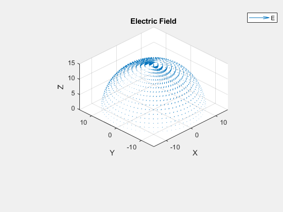
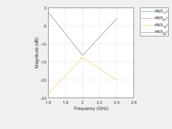
Plot the radiation pattern and electric field for this measuredAntenna at 2GHz, while plot S-parameters over the entire frequency range.
pattern(mesAnt,fRange(2),Type="efield")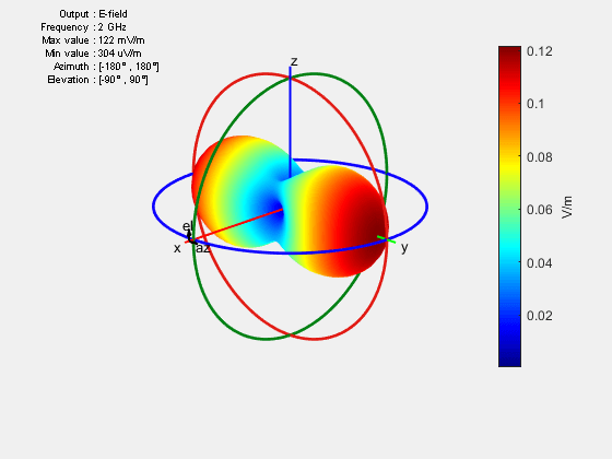
EHfields(mesAnt,fRange(2))
sp = sparameters(mesAnt,fRange);
rfplot(sp)
This example shows how to import radiation pattern data from a .ffd file to workspace and visualize it. The .ffd file contains far-field data generated by the HFSS™ software. The data is visualized using object functions of the measuredAntenna object.
Load the radiation pattern data from the .ffd file into the workspace by using the loadData helper function (defined in the supporting function section of this example). Specify the coordinate system angle convention used for this data in the .ffd file.
fileName = sprintf("RefFFDdata.ffd"); CoordinateSystem ="Phi-Theta"; [theta1,phi1,numFreqs,Etheta,Ephi,freqs] = loadData(fileName,CoordinateSystem); if CoordinateSystem == "Phi-Theta" elev = 90 - theta1; else elev = theta1; end
Calculate the number of data points.
numPt = numel(theta1)*numel(phi1);
Extract the electric field data from the data in the workspace.
ESph = [Ephi;Etheta;zeros(numPt,3)];
eField = reshape(ESph,numPt,3,numFreqs);
Calculate the spherical coordinates of the electric field points.
lambda = 3e8/max(freqs);
radius = 100*lambda*ones(numPt,1);
[theta,phi] = meshgrid(elev,phi1);
phi = phi(:);
theta = theta(:);
direction = [phi theta radius];
Create a measuredAntenna object with number of ports equal to those present in the .ffd file data. Set the E property value to eField. Set the Direction property using calculated spherical coordinates. Set the Azimuth property to phi1 and Elevation property to elev. Specify the phase center. This example assumes the phase center at (0,0,0). Set the FieldFrequency property using the frequencies of the electric field data.
mAnt = measuredAntenna(NumPorts=1);
mAnt.E = eField;
mAnt.Direction = direction;
mAnt.PhaseCenter = [0 0 0];
mAnt.FieldFrequency = freqs;
mAnt.Azimuth = phi1;
mAnt.Elevation = elev;
mAnt.FieldCoordinate = 'polar';
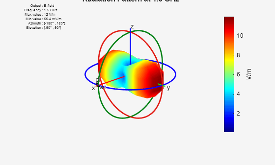
Visualize the radiation patterns at the individual frequencies.
for i=1:numFreqs
figure
pattern(mAnt,freqs(i))
title(strcat("Radiation Pattern at ",num2str(freqs(i)/1e9)," GHz"))
end


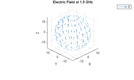
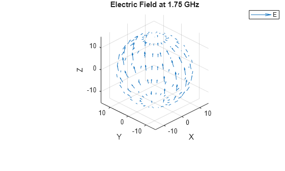
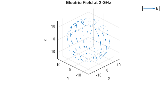
Visualize the corresponding electric fields.
for i=1:numFreqs
figure
EHfields(mAnt,freqs(i))
title(strcat("Electric Field at ",num2str(freqs(i)/1e9)," GHz"))
end
Supporting Function
The loadData helper function extracts the number of frequencies, angle values for the data points, and the electric field values from the .ffd file.
function [theta1,phi1,numFreqs,Etheta,Ephi,freqs] = loadData(fileName,CoordinateSystem)
fid = fopen(fileName);

if CoordinateSystem == "Phi-Theta"
    numHeaderLines = 3;
else
    textscan(fid,'%s',1);
    numHeaderLines = 4;
end

data = num2cell(fscanf(fid,'%d',3));
theta1 = linspace(data{:});
data = num2cell(fscanf(fid,'%d',3));
phi1 = linspace(data{:});
C1 = textscan(fid,'%s %d',1);
numFreqs = C1{2};
fclose(fid);

Mfull = readmatrix(fileName,FileType="text",NumHeaderLines=numHeaderLines);
freqs = Mfull(isnan(Mfull(:,1)),2);
MData = Mfull(~isnan(Mfull(:,1)),:);
Etheta = reshape(MData(:,1) + 1j*MData(:,2),length(phi1)*length(theta1),[]);
Ephi = reshape(MData(:,3) + 1j*MData(:,4),length(phi1)*length(theta1),[]);
end
This example shows how to use measuredAntenna object in the Antenna block to model a measured antenna or array characterized by means of its S-parameters and frequency dependent far-field radiation pattern including both polarization components. The measuredAntenna object lets you replace the physical antennas from the antenna catalog with measured field data of the antenna. This example extracts data from a linear array to create a measuredAntenna object using hcreate_mAnt helper function.
System Configuration
Define the carrier frequency in Hz and set it in these parameters:
Radiated carrier frequency parameter in the Transmit Antenna block
Incident carrier frequency parameter in the Receiver Antenna block
Carrier frequencies parameter in the Inport and Outport blocks
FreqCarrier = 5e9;
Define gain for the Gain block. This Gain block acts as a free-space path-loss channel.
lambdaCarrier = physconst('lightspeed')/FreqCarrier; %[m]
Define the input impedance of the low noise amplifier (LNA) in ohms.
Zin_r =71.3819 - 1j*2.1795;
Define the available input power in dBm for the two RF transmitter chains and assign the variables to Pin 1 and Pin 2 in the Constant block.
Pin1 = -30;
Pin2 = -30;
Create a linear antenna array and extract data from it to create a measuredAntenna object. The data extracted from the linear array is a substitute of real-world measured data that can be inputted by changing the hcreate_mAnt helper function so as to read the embedded electric fields from data file.
dist = lambdaCarrier*0.5;
d1 = design(dipole,FreqCarrier);
antElems = [d1 copy(d1)];
la = linearArray('Element',antElems,'ElementSpacing',dist);
la.TiltAxis = [0 1 0];
la.Tilt = 90;
freqRange = (4.5:0.05:5.5)*1e9;
[mAnt,R] = hcreate_mAnt(la,freqRange);
Compute impedances in ohms for PA and PA1 Amplifier blocks in the transmitter.
z = impedance(la,freqRange);
z = z(freqRange==FreqCarrier,:);
Zin_t1 = z(1);
Zin_t2 = z(2);
Simulate Model
Open and simulate the measuredAnt.slx model. Observe the output power at the receiver.
open_system("measuredAnt.slx")
sim("measuredAnt.slx");

Version History
Introduced in R2023aPerform field and port analysis using pattern, EHfields, and sparameters on:
The electric field and S-parameters data of an antenna
The total electric field, embedded electric field, and S-parameters data of an array
measured at multiple frequencies.
See Also
Objects
MATLAB Command
You clicked a link that corresponds to this MATLAB command:
Run the command by entering it in the MATLAB Command Window. Web browsers do not support MATLAB commands.
Website auswählen
Wählen Sie eine Website aus, um übersetzte Inhalte (sofern verfügbar) sowie lokale Veranstaltungen und Angebote anzuzeigen. Auf der Grundlage Ihres Standorts empfehlen wir Ihnen die folgende Auswahl: .
Sie können auch eine Website aus der folgenden Liste auswählen:
So erhalten Sie die bestmögliche Leistung auf der Website
Wählen Sie für die bestmögliche Website-Leistung die Website für China (auf Chinesisch oder Englisch). Andere landesspezifische Websites von MathWorks sind für Besuche von Ihrem Standort aus nicht optimiert.
Amerika
- América Latina (Español)
- Canada (English)
- United States (English)
Europa
- Belgium (English)
- Denmark (English)
- Deutschland (Deutsch)
- España (Español)
- Finland (English)
- France (Français)
- Ireland (English)
- Italia (Italiano)
- Luxembourg (English)
- Netherlands (English)
- Norway (English)
- Österreich (Deutsch)
- Portugal (English)
- Sweden (English)
- Switzerland
- United Kingdom (English)