M-FSK Demodulator Baseband
Demodulate FSK-modulated data
Libraries:
Communications Toolbox /
Modulation /
Digital Baseband Modulation /
FM
Description
The M-FSK Demodulator Baseband block demodulates a signal that was modulated using the M-ary frequency shift keying (M-FSK) method. The input and output are discrete-time signals.
Examples
Pass a 2-FSK-modulated signal through an additive white Gaussian noise (AWGN) channel. Demodulate the received signal and calculate the symbol error rate (SER).
The cm_2fsk_mod_demod model 2-FSK-modulates a random binary signal, applies AWGN, and then 2-FSK-demodulates the signal. An Error Rate Calculation block computes the SER. In the Error Rate Calculation block, a setting of 1 for the Receive delay parameter accounts for a 1 sample delay.
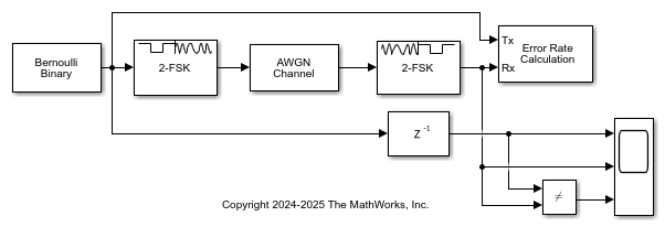
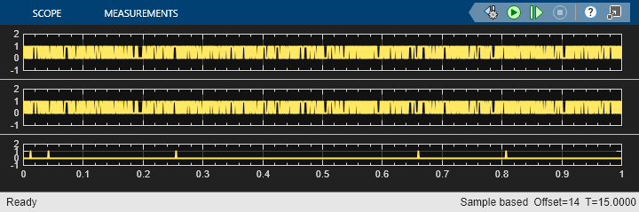
Display the computed SER with Es/N0 set to 10. A Scope (Simulink) block plots the time domain input and demodulated signals, and a signal that indicates when the two signals are not equal.
With EsN0 set to 10, SER = 0.004611
M-FSK-modulate and -demodulate input integer and binary data. Each integer or group of log2(M) bits corresponds to one symbol, where M represents the M-ary number parameter value. Compute the expected signal lengths for the input and output signals. Display the expected and resulting lengths for the input and output signals.
The cm_fsk_mod_demod_bin_int model has two parallel processing paths that modulate and demodulate the input data.
The modulator and demodulator pairs are configured for 8-ary modulation order, 100 Hz frequency separation, 21 samples per frame, and 10 samples per symbol. The model initializes the variables that configure the block parameters by using the PreLoadFcn callback function. For more information, see Model Callbacks (Simulink).
The upper path modulates data by using an 8-FSK Modulator block configured to accept integer data, and then demodulates the data and outputs binary and integer data from separate 8-FSK Demodulator blocks.
The lower path modulates data by using an 8-FSK Modulator block configured to accept binary data, and also demodulates the data and outputs binary and integer data from separate 8-FSK Demodulator blocks.
Run the model and compute the expected and resulting input and output signal lengths. Display the signal lengths to confirm that the results match the expected lengths.

Display the expected input and output lengths for a binary input signal.
Nbit  Nsym  Nbout  Niout
 693   2310   693   231
Display the resulting input and output lengths for a binary input signal.
 bit   sym   bout   iout
 693   2310   693   231
Display the expected input and output lengths for an integer input signal.
Nint  Nsym  Nibout  Niiout
 231   2310   693   231
Display the resulting input and output lengths for an integer input signal.
 bit   sym   bout   iout
 231   2310   693   231
Ports
Input
Output
Parameters
Block Characteristics
Data Types |
|
Multidimensional Signals |
|
Variable-Size Signals |
|
More About
Tips
The M-FSK Demodulator Baseband block implements a noncoherent energy detector. To obtain the same BER performance as that of coherent FSK demodulation, use the CPFSK Demodulator Baseband block.
Algorithms
Demodulation of M-FSK-modulated signals is performed by using noncoherent detection, which configures an energy detector that does not exploit phase measurements. The demodulator knows that M possible waveforms were transmitted and must decide which is received during each time duration T.
As described in Sklar [1], the general analytical expression for M-FSK modulation is
E is the symbol energy.
T is the symbol time duration.
ωi is the frequency term that has M discrete values.
M is the modulation order and specifies the number of waveforms.
ϕ is the phase offset.
The noncoherent energy detector of the M-FSK demodulator selects decision regions for each ωi waveform based on which decision region yields the maximum output.
For more details, see the Noncoherent Detection of FSK section in Sklar, [1].
References
[1] Sklar, Bernard. Digital Communications: Fundamentals and Applications. 2nd ed. Upper Saddle River, NJ: Prentice-Hall PTR, 2001.
Extended Capabilities
Version History
Introduced before R2006a