Configure Elements of AUTOSAR Adaptive Software Component for Simulink Modeling Environment
After you create a representation of the AUTOSAR adaptive software component in the Simulink® Editor, configure elements of the software component for use in Simulink. The configuration maps AUTOSAR adaptive software component elements to Simulink modeling elements.
AUTOSAR Blockset software reduces the effort of setting up a configuration by providing an AUTOSAR Component Quick Start tool. If necessary, you can modify the initial configuration by using the Code Mappings editor and the AUTOSAR Dictionary.
Set Up an Initial Component Configuration
Set up an initial configuration of an AUTOSAR adaptive software component by using the AUTOSAR Component Quick Start tool.
Open your saved version of the example model
my_autosar_LaneGuidance.Set model configuration parameter System target file to
autosar_adaptive.tlc.Run the AUTOSAR Component Quick Start tool. From the Apps tab, open the AUTOSAR Component Designer app. When you open the app for an unmapped model that is configured with an AUTOSAR system target file, the AUTOSAR Component Quick Start tool runs.
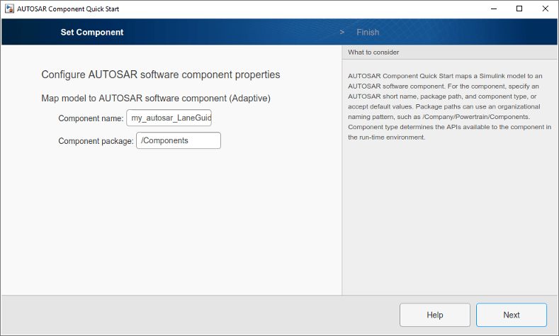
Advance through the steps of the AUTOSAR Component Quick Start tool. Each step prompts you for input that the tool uses to configure your AUTOSAR software component for the Simulink environment. For this tutorial, use the defaults.
After you click Finish, the tool:
Creates a mapping between elements of the AUTOSAR adaptive software component and Simulink model elements.
Opens the model in the Simulink Editor AUTOSAR Code perspective. The AUTOSAR Code perspective displays the model and directly below the model, the Code Mappings editor.
Displays the AUTOSAR software component mappings in the Code Mappings editor, which you can use to customize the configuration.
Save the model.
Customize Component Configuration
The AUTOSAR Component Quick Start tool sets up an initial configuration for an AUTOSAR adaptive software component. To refine or make changes to an existing component configuration, use the Code Mappings editor and the AUTOSAR Dictionary.
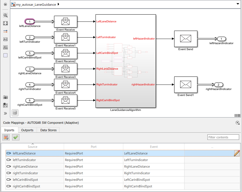
In a tabbed table format, the Code Mappings editor displays Simulink model inports and outports. Map Simulink inports and outports to AUTOSAR adaptive software component ports in the editor. AUTOSAR adaptive software component ports are defined in the AUTOSAR standard.
If not already open, open model
my_autosar_LaneGuidance.In the Code Mappings editor, examine the mapping of Simulink inports and outports to AUTOSAR ports and events. In each tab, you can select model elements and modify their AUTOSAR mapping and attributes. Modifications are reflected in generated ARXML descriptions and C code.
Select the Inports tab. For each Simulink inport, the editor lists the corresponding AUTOSAR port type and event. For example, Simulink inport
leftLaneDistanceis mapped to an AUTOSAR required port and eventLeftLaneDistance.With a Code Mappings editor row selected, open the Property Inspector. Check whether you need to reconfigure data types or other attributes of model data. For example, verify that event data is configured correctly for the design. For this tutorial, make no changes.
Configure AUTOSAR Adaptive Software Component Elements from AUTOSAR Standard Perspective
Configure AUTOSAR software component elements from the perspective of the AUTOSAR standard perspective by using the AUTOSAR Dictionary.
If not already open, open model
my_autosar_LaneGuidance.Open the AUTOSAR Dictionary. In the Code Mappings editor, click the AUTOSAR Dictionary button
 . The AUTOSAR Dictionary opens in the
AUTOSAR view, which corresponds to the Simulink element that you last selected and mapped in the Code Mappings
editor. If you selected and mapped a Simulink inport, the dictionary opens in
RequiredPorts view and displays the AUTOSAR port
that you mapped the inport to.
. The AUTOSAR Dictionary opens in the
AUTOSAR view, which corresponds to the Simulink element that you last selected and mapped in the Code Mappings
editor. If you selected and mapped a Simulink inport, the dictionary opens in
RequiredPorts view and displays the AUTOSAR port
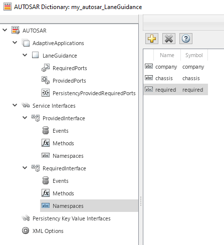
that you mapped the inport to.In a tree format, the AUTOSAR Dictionary displays the mapped AUTOSAR software component and its elements, interfaces, and XML options.
Use the AUTOSAR Dictionary to further customize component configurations. For example, you can use the dictionary to:
Expand service interface nodes to examine AUTOSAR events created during the default component mapping.
Define a unique namespace for each service interface. The code generator uses the defined namespaces when producing C++ code for the model.
Configure characteristics of exported AUTOSAR XML.
In the left pane of the dictionary, expand the tree nodes and explore what is defined for the model.
For this tutorial, add namespaces for service interfaces
ProvidedInterfaceandRequiredInterface.In the left pane of the dictionary, expand the Service Interfaces and ProvidedInterface nodes.
Select Namespaces.
In the right pane, click the plus sign.
Set Name and Symbol to
company.Add namespace entries for
chassisandprovided.Add
company,chassis, andrequirednamespace entries for the RequiredInterface node.
Close the dictionary.
Save the model.
Next, simulate the AUTOSAR software component.