Add AUTOSAR Compositions and Components and Link Component Implementations
After you create an AUTOSAR architecture model, you begin authoring the top level of an AUTOSAR software design. Use the composition editor and the Simulink® Toolstrip Modeling tab to add and connect AUTOSAR compositions and components.
In the previous step, you opened a local working example folder and created an empty AUTOSAR architecture model. If necessary, repeat the step to open the working folder and create the empty model.
As you construct a throttle position control application, you can refer to example
model autosar_tpc_composition, which shows the end result. Open the
example model by entering this command in your MATLAB® Command
Window:
openExample("autosar_tpc_composition");Add Compositions and Components to Architecture Canvas
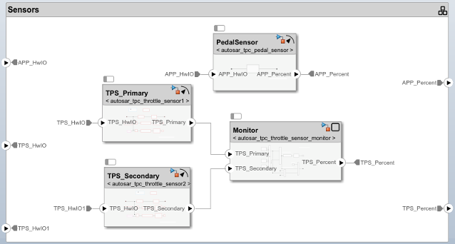
Typically, an AUTOSAR composition contains a set of AUTOSAR components and compositions with a shared purpose. As part of constructing a throttle position control application, this tutorial places four sensor components in a sensors composition. Note that the model is configured for classic architecture modeling by setting the Platform selection on the toolstrip to Classic Platform.
To add the sensors composition and its components to the AUTOSAR architecture model:
In the architecture model canvas, add a Software Composition block and name it Sensors. For example, on the Modeling tab, select Software Composition and insert a Software Composition block in the canvas. In the highlighted name field, enter
Sensors.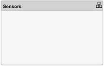
To populate a composition, you open the Software Composition block and add software components.
Open the
Sensorsblock so that the model canvas shows the composition content. Inside the composition, add AUTOSAR software components namedTPS_Primary,TPS_Secondary,Monitor, andPedalSensor. For example, on the Modeling tab, you can select Classic Component to create each one.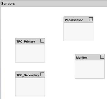
Next, you add require and provide ports to the components, and then connect the component ports to other component blocks or to composition root ports. To add component require and provide ports, this tutorial links software component blocks to implementation models in which the ports are already defined.
Define Component Behavior by Linking Implementation Models
The behavior of an AUTOSAR application is defined by its AUTOSAR software components. After you insert software component blocks in an AUTOSAR architecture model, you can add Simulink behavior to the components. For each software component block, you can:
Create a model based on the block interface.
Link to an implementation model.
Create a model from an AUTOSAR XML (ARXML) component description.
For convenience, this tutorial provides a Simulink implementation model for each AUTOSAR component:
autosar_tpc_throttle_sensor1.slxfor componentTPS_Primaryautosar_tpc_throttle_sensor2.slxfor componentTPS_Secondaryautosar_tpc_throttle_sensor_monitor.slxfor componentMonitorautosar_tpc_pedal_sensor.slxfor componentPedalSensor
To add Simulink behavior to the components:
In the architecture model, open the
Sensorscomposition block if it is not already open. Inside the composition, link each AUTOSAR sensor component to a Simulink model that implements its behavior.For example, select the
TPS_Primarycomponent block, place your cursor over the displayed ellipsis, and select the cue Link to Model.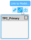
In the Link to Model dialog box, navigate to implementation model
autosar_tpc_throttle_sensor1.slx.
To link the component to the implementation model, click OK.
Link components
TPS_Secondary,Monitor, andPedalSensorto their implementation models. After you link each model, you can resize the associated component block to better display the component ports.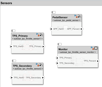
Linking a software component block to a specified implementation model updates the block and model interfaces to match. If you link to a model that uses root Inport and Outport blocks, the software converts the model signal ports to bus ports. To view the model content, open the component block.
Connect the components to each other and to composition root ports.
To interconnect components, drag a line from a component provider port to another component receiver port, or on the Modeling toolstrip in the Connect section click the Smart Connect button.
To connect components to root-level ports on
Sensorscomposition boundary, click and drag from a component port to theSensorscomposition boundary.
Optionally, to exactly match the root port naming in the example model
autosar_tpc_composition, rename portsTPS_HwIOandTPS_HwIO1toTPS1_HwIOandTPS2_HwIO.
Complete Architecture Model Top Level
To complete the throttle position control application:
Return to the top level of the architecture model. Add two Classic Component blocks and name them
ControllerandActuator.Link the AUTOSAR components
ControllerandActuatorto their Simulink implementation models,autosar_tpc_controller.slxandautosar_tpc_actuator.slx.Connect the
Sensorscomposition,Controllercomponent, andActuatorcomponent to each other and to the architecture model boundary.
Interfaces and data types are defined in data dictionary
tpc_interfaces.sldd. Link this data dictionary to the software architecture model. On the Modeling tab, in the Design section, select Interfaces and Types > Link Existing Dictionary.To check for interface or data type issues, update the architecture model. On the Modeling tab, select Update Model. If any issues are found, compare your model with example model
autosar_tpc_composition.Save the model with a unique name, such as
myTPC_Composition.slx.
Next, simulate the behavior of the aggregated components in the AUTOSAR architecture model.