SI Core Engine
Spark-ignition engine from intake to exhaust port
Libraries:
Powertrain Blockset /
Propulsion /
Combustion Engine Components /
Core Engine
Description
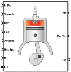
The SI Core Engine block implements a spark-ignition (SI) engine from intake to exhaust port. You can use the block in larger vehicle models, hardware-in-the-loop (HIL) engine control design, or vehicle-level fuel economy and performance simulations.
The SI Core Engine block calculates:
Brake torque
Fuel flow
Port gas mass flow, including exhaust gas recirculation (EGR)
Air-fuel ratio (AFR)
Exhaust temperature and exhaust mass flow rate
Engine-out (EO) exhaust emissions
Hydrocarbon (HC)
Carbon monoxide (CO)
Nitric oxide and nitrogen dioxide (NOx)
Carbon dioxide (CO2)
Particulate matter (PM)
Air Mass Flow
To calculate engine air mass flow, configure the SI engine to use either of these air mass flow models.
| Air Mass Flow Model | Description |
|---|---|
| SI Engine Speed-Density Air Mass Flow Model |
Uses the speed-density equation to calculate the engine air mass flow, relating the engine air mass flow to the intake manifold pressure and engine speed. Consider using this air mass flow model in engines with fixed valvetrain designs. |
| SI Engine Dual-Independent Cam Phaser Air Mass Flow Model |
To calculate the engine air mass flow, the dual-independent cam phaser model uses:
In contrast to typical embedded air mass flow calculations based on direct air mass flow measurement with an air mass flow (MAF) sensor, this air mass flow model offers:
|
Brake Torque
To calculate the brake torque, configure the SI engine to use either of these torque models.
| Brake Torque Model | Description |
|---|---|
| SI Engine Torque Structure Model | For the structured brake torque calculation, the SI engine uses tables for the inner torque, friction torque, optimal spark, spark efficiency, and lambda efficiency. If you select Crank angle pressure and torque on the block Torque tab, you can:
|
| SI Engine Simple Torque Model |
For the simple brake torque calculation, the SI engine block uses a torque lookup table map that is a function of engine speed and load. |
Fuel Flow
To calculate the fuel flow, the SI Core Engine block uses fuel injector characteristics and fuel injector pulse-width.
To calculate the fuel economy for high-fidelity models, the block uses the volumetric fuel flow.
The equation uses these variables.
| Fuel mass flow, g/s | |
| Engine rotational speed, rad/s | |
Crankshaft revolutions per power stroke, rev/stroke | |
Fuel injector slope, mg/ms | |
Fuel injector pulse-width, ms | |
Number of engine cylinders | |
| N | Engine speed, rpm |
| Sgfuel | Specific gravity of fuel |
| Qfuel | Volumetric fuel flow |
The block uses the internal signal FlwDir to track the direction of the flow.
Air-Fuel Ratio
To calculate the air-fuel (AFR) ratio, the CI Core Engine and SI Core Engine blocks implement this equation.
The CI Core Engine uses this equation to calculate the relative AFR.
To calculate the exhaust gas recirculation (EGR), the blocks implement this equation. The calculation expresses the EGR as a percent of the total intake port flow.
The equations use these variables.
Air-fuel ratio | |
| AFRs | Stoichiometric air-fuel ratio |
Engine air mass flow | |
Fuel mass flow | |
λ | Relative AFR |
| yintk,b | Intake burned mass fraction |
| EGRpct | EGR percent |
Recirculated burned gas mass flow rate |
Exhaust
The block calculates the:
Exhaust gas temperature
Exhaust gas-specific enthalpy
Exhaust gas mass flow rate
Engine-out (EO) exhaust emissions:
Hydrocarbon (HC)
Carbon monoxide (CO)
Nitric oxide and nitrogen dioxide (NOx)
Carbon dioxide (CO2)
Particulate matter (PM)
The exhaust temperature determines the specific enthalpy.
The exhaust mass flow rate is the sum of the intake port air mass flow and the fuel mass flow.
To calculate the exhaust emissions, the block multiplies the emission mass fraction by the exhaust mass flow rate. To determine the emission mass fractions, the block uses lookup tables that are functions of the engine torque and speed.
The fraction of air and fuel entering the intake port, injected fuel, and stoichiometric AFR determine the air mass fraction that exits the exhaust.
If the engine is operating at the stoichiometric or fuel rich AFR, no air exits the exhaust. Unburned hydrocarbons and burned gas comprise the remainder of the exhaust gas. This equation determines the exhaust burned gas mass fraction.
The equations use these variables.
Engine exhaust temperature | |
Exhaust manifold inlet-specific enthalpy | |
Exhaust gas specific heat | |
Intake port air mass flow rate | |
Fuel mass flow rate | |
Exhaust mass flow rate | |
Intake fuel mass fraction | |
| yexh,i | Exhaust mass fraction for i = CO2, CO, HC, NOx, air, burned gas, and PM |
Exhaust mass flow rate for i = CO2, CO, HC, NOx, air, burned gas, and PM | |
| Tbrake | Engine brake torque |
| N | Engine speed |
| yexh,air | Exhaust air mass fraction |
| yexh,b | Exhaust air burned mass fraction |
Power Accounting
For the power accounting, the block implements equations that depend on Torque model.
When you set Torque model to Simple Torque Lookup, the block implements these equations.
| Bus Signal | Description | Equations | ||
|---|---|---|---|---|
|
|
| Intake heat flow | |
PwrExhHeatFlw | Exhaust heat flow | |||
PwrCrkshft | Crankshaft power | |||
| PwrFuel | Fuel input power | ||
PwrLoss | All losses | |||
| Not used | |||
When you set Torque model to Torque Structure, the block implements these equations.
| Bus Signal | Description | Equations | ||
|---|---|---|---|---|
|
|
| Intake heat flow | |
PwrExhHeatFlw | Exhaust heat flow | |||
PwrCrkshft | Crankshaft power | |||
| PwrFuel | Fuel input power | ||
PwrFricLoss | Friction loss | |||
PwrPumpLoss | Pumping loss | |||
PwrHeatTrnsfrLoss | Heat transfer loss | |||
| Not used | |||
| hexh | Exhaust manifold inlet-specific enthalpy |
| hintk | Intake port specific enthalpy |
Intake port air mass flow rate | |
Fuel mass flow rate | |
Exhaust mass flow rate | |
| ω | Engine speed |
| Tbrake | Brake torque |
| Tpump | Engine pumping work offset to inner torque |
| Tfric | Engine friction torque |
| LHV | Fuel lower heating value |
Examples

Build Conventional Vehicle Model
Build a vehicle with an internal combustion engine using the conventional vehicle reference application.

Calibrate, Validate, and Optimize SI Engine with Dynamometer Test Harness
Simulate a spark-ignition (SI) engine and controller under a dynamometer test harness using the SI engine dynamometer reference application.
Ports
Input
Output
Parameters
Block Options
To calculate engine air mass flow, configure the SI engine to use either of these air mass flow models.
| Air Mass Flow Model | Description |
|---|---|
| SI Engine Speed-Density Air Mass Flow Model |
Uses the speed-density equation to calculate the engine air mass flow, relating the engine air mass flow to the intake manifold pressure and engine speed. Consider using this air mass flow model in engines with fixed valvetrain designs. |
| SI Engine Dual-Independent Cam Phaser Air Mass Flow Model |
To calculate the engine air mass flow, the dual-independent cam phaser model uses:
In contrast to typical embedded air mass flow calculations based on direct air mass flow measurement with an air mass flow (MAF) sensor, this air mass flow model offers:
|
Programmatic Use
To set the block
parameter value programmatically, use the set_param
function.
To get the block
parameter value programmatically, use the get_param
function.
| Parameter: | AirMassFlowOptionPopup |
| Values: | Dual-Independent Variable Cam
Phasing (default) | Simple Speed-Density |
| Data Types: | character vector |
Dependencies
The table summarizes the parameter dependencies.
| Air Mass Flow Model | Enables Parameters |
|---|---|
| Cylinder volume at intake valve close table, f_vivc Cylinder volume intake cam phase breakpoints, f_vivc_icp_bpt Cylinder trapped mass correction factor, f_tm_corr Normalized density breakpoints, f_tm_corr_nd_bpt Engine speed breakpoints, f_tm_corr_n_bpt Air mass flow, f_mdot_air Exhaust cam phase breakpoints, f_mdot_air_ecp_bpt Trapped mass flow breakpoints, f_mdot_trpd_bpt Air mass flow correction factor, f_mdot_air_corr Engine load breakpoints for air mass flow correction, f_mdot_air_corr_ld_bpt Engine speed breakpoints for air mass flow correction, f_mdot_air_n_bpt |
| Speed-density volumetric efficiency, f_nv Speed-density intake manifold pressure breakpoints, f_nv_prs_bpt Speed-density engine speed breakpoints, f_nv_n_bpt |
To calculate the brake torque, configure the SI engine to use either of these torque models.
| Brake Torque Model | Description |
|---|---|
| SI Engine Torque Structure Model | For the structured brake torque calculation, the SI engine uses tables for the inner torque, friction torque, optimal spark, spark efficiency, and lambda efficiency. If you select Crank angle pressure and torque on the block Torque tab, you can:
|
| SI Engine Simple Torque Model |
For the simple brake torque calculation, the SI engine block uses a torque lookup table map that is a function of engine speed and load. |
Programmatic Use
To set the block
parameter value programmatically, use the set_param
function.
To get the block
parameter value programmatically, use the get_param
function.
| Parameter: | TrqOptionPopup |
| Values: | Torque
Structure (default) | Simple Torque Lookup |
| Data Types: | character vector |
Dependencies
The table summarizes the parameter dependencies.
| Torque Model | Enables Parameters |
|---|---|
| Inner torque table, f_tq_inr Friction torque table, f_tq_fric Engine temperature modifier on friction torque, f_fric_temp_mod Engine temperature modifier breakpoints, f_fric_temp_bpt Pumping work table, f_tq_pump Optimal spark table, f_sa_opt Inner torque load breakpoints, f_tq_inr_l_bpt Inner torque speed breakpoints, f_tq_inr_n_bpt Spark efficiency table, f_m_sa Spark retard from optimal, f_del_sa_bpt Lambda efficiency, f_m_lam Lambda breakpoints, f_m_lam_bpt |
| Torque table, f_tq_nl Torque table load breakpoints, f_tq_nl_l_bpt Torque table speed breakpoints, f_tq_nl_n_bpt |
Air
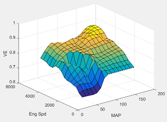
The engine volumetric efficiency lookup table, , is a function of intake manifold absolute pressure and engine speed
where:
is engine volumetric efficiency, dimensionless.
MAP is intake manifold absolute pressure, in KPa.
N is engine speed, in rpm.
Programmatic Use
To set the block
parameter value programmatically, use the set_param
function.
To get the block
parameter value programmatically, use the get_param
function.
| Parameter: | f_nv |
| Values: | array |
| Data Types: | double |
Dependencies
To enable this parameter, for the Air mass flow
model parameter, select Simple
Speed-Density.
Intake manifold pressure breakpoints for speed-density volumetric efficiency lookup table, in KPa.
Programmatic Use
To set the block
parameter value programmatically, use the set_param
function.
To get the block
parameter value programmatically, use the get_param
function.
| Parameter: | f_nv_prs_bpt |
| Values: | array |
| Data Types: | double |
Dependencies
To enable this parameter, for the Air mass flow
model parameter, select Simple
Speed-Density.
Engine speed breakpoints for speed-density volumetric efficiency lookup table, in rpm.
Programmatic Use
To set the block
parameter value programmatically, use the set_param
function.
To get the block
parameter value programmatically, use the get_param
function.
| Parameter: | f_nv_n_bpt |
| Values: | array |
| Data Types: | double |
Dependencies
To enable this parameter, for the Air mass flow
model parameter, select Simple
Speed-Density.
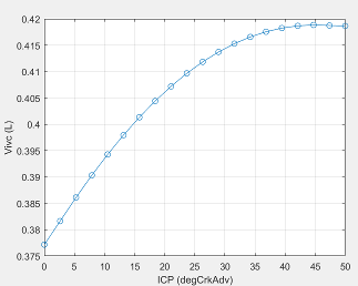
The cylinder volume at intake valve close table (IVC), is a function of the intake cam phaser angle
where:
is cylinder volume at IVC, in L.
is intake cam phaser angle in crank degrees of advance relative to the intake phaser park position.
Programmatic Use
To set the block
parameter value programmatically, use the set_param
function.
To get the block
parameter value programmatically, use the get_param
function.
| Parameter: | f_vivc |
| Values: | array |
| Data Types: | double |
Dependencies
To enable this parameter, for the Air mass flow
model parameter, select Dual-Independent
Variable Cam Phasing.
Cylinder volume intake cam phase breakpoints, in L.
Programmatic Use
To set the block
parameter value programmatically, use the set_param
function.
To get the block
parameter value programmatically, use the get_param
function.
| Parameter: | f_vivc_icp_bpt |
| Values: | vector |
| Data Types: | double |
Dependencies
To enable this parameter, for the Air mass flow
model parameter, select Dual-Independent
Variable Cam Phasing.
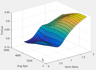
The trapped mass correction factor table, , is a function of the normalized density and engine speed
where:
, is trapped mass correction multiplier, dimensionless.
is normalized density, dimensionless.
N is engine speed, in rpm.
Programmatic Use
To set the block
parameter value programmatically, use the set_param
function.
To get the block
parameter value programmatically, use the get_param
function.
| Parameter: | f_tm_corr |
| Values: | array |
| Data Types: | double |
Dependencies
To enable this parameter, for the Air mass flow
model parameter, select Dual-Independent
Variable Cam Phasing.
Normalized density breakpoints, dimensionless.
Programmatic Use
To set the block
parameter value programmatically, use the set_param
function.
To get the block
parameter value programmatically, use the get_param
function.
| Parameter: | f_tm_corr_nd_bpt |
| Values: | vector |
| Data Types: | double |
Dependencies
To enable this parameter, for the Air mass flow
model parameter, select Dual-Independent
Variable Cam Phasing.
Engine speed breakpoints, in rpm.
Programmatic Use
To set the block
parameter value programmatically, use the set_param
function.
To get the block
parameter value programmatically, use the get_param
function.
| Parameter: | f_tm_corr_n_bpt |
| Values: | vector |
| Data Types: | double |
Dependencies
To enable this parameter, for the Air mass flow
model parameter, select Dual-Independent
Variable Cam Phasing.
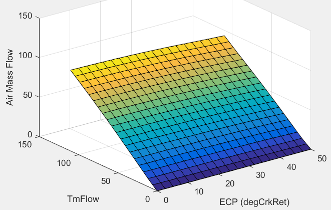
The phaser intake mass flow model lookup table is a function of exhaust cam phaser angles and trapped air mass flow
where:
is engine intake port mass flow at arbitrary cam phaser angles, in g/s.
is exhaust cam phaser angle in crank degrees of retard relative to the exhaust phaser park position.
is flow rate equivalent to corrected trapped mass at the current engine speed, in g/s.
Programmatic Use
To set the block
parameter value programmatically, use the set_param
function.
To get the block
parameter value programmatically, use the get_param
function.
| Parameter: | f_mdot_intk |
| Values: | array |
| Data Types: | double |
Dependencies
To enable this parameter, for the Air mass flow
model parameter, select Dual-Independent
Variable Cam Phasing.
Exhaust cam phaser breakpoints for air mass flow lookup table, in crank degrees of retard relative to park.
Programmatic Use
To set the block
parameter value programmatically, use the set_param
function.
To get the block
parameter value programmatically, use the get_param
function.
| Parameter: | f_mdot_air_ecp_bpt |
| Values: | vector |
| Data Types: | double |
Dependencies
To enable this parameter, for the Air mass flow
model parameter, select Dual-Independent
Variable Cam Phasing.
Trapped mass flow breakpoints for air mass flow lookup table, in g/s.
Programmatic Use
To set the block
parameter value programmatically, use the set_param
function.
To get the block
parameter value programmatically, use the get_param
function.
| Parameter: | f_mdot_trpd_bpt |
| Values: | vector |
| Data Types: | double |
Dependencies
To enable this parameter, for the Air mass flow
model parameter, select Dual-Independent
Variable Cam Phasing.
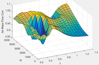
The intake air mass flow correction lookup table, , is a function of ideal load and engine speed
where:
is engine load (normalized cylinder air mass) at arbitrary cam phaser angles, uncorrected for final steady-state cam phaser angles, dimensionless.
N is engine speed, in rpm.
is engine intake air mass flow final correction at steady-state cam phaser angles, in g/s.
is engine intake port mass flow at arbitrary cam phaser angles, in g/s.
Programmatic Use
To set the block
parameter value programmatically, use the set_param
function.
To get the block
parameter value programmatically, use the get_param
function.
| Parameter: | f_mdot_air_corr |
| Values: | array |
| Data Types: | double |
Dependencies
To enable this parameter, for the Air mass flow
model parameter, select Dual-Independent
Variable Cam Phasing.
Engine load breakpoints for air mass flow final correction, dimensionless.
Programmatic Use
To set the block
parameter value programmatically, use the set_param
function.
To get the block
parameter value programmatically, use the get_param
function.
| Parameter: | f_mdot_air_corr_ld_bpt |
| Values: | vector |
| Data Types: | double |
Dependencies
To enable this parameter, for the Air mass flow
model parameter, select Dual-Independent
Variable Cam Phasing.
Engine speed breakpoints for air mass flow final correction, in rpm.
Programmatic Use
To set the block
parameter value programmatically, use the set_param
function.
To get the block
parameter value programmatically, use the get_param
function.
| Parameter: | f_mdot_air_n_bpt |
| Values: | vector |
| Data Types: | double |
Dependencies
To enable this parameter, for the Air mass flow
model parameter, select Dual-Independent
Variable Cam Phasing.
Torque
For the simple torque lookup table model, the SI engine uses a lookup table map that is a function of engine speed and load, , where:
is engine brake torque after accounting for spark advance, AFR, and friction effects, in N·m.
L is engine load, as a normalized cylinder air mass, dimensionless.
N is engine speed, in rpm.
The simple torque lookup model assumes that the calibration has negative torque values to indicate the non-firing engine load (L) versus speed (N) condition. The calibrated table (L-by-N) contains the non-firing data in the first table row (1-by-N). When the fuel delivered to the engine is zero, the model uses the data in the first table row (1-by-N) at or above 100 AFR. 100 AFR results from fuel cutoff or very lean operation where combustion cannot occur.
Dependencies
To enable this parameter, for the Torque model parameter,
select Simple Torque Lookup.
Engine load breakpoints, L, dimensionless.
Dependencies
To enable this parameter, for the Torque model parameter,
select Simple Torque Lookup.
Engine speed breakpoints, N, in rpm.
Dependencies
To enable this parameter, for the Torque model parameter,
select Simple Torque Lookup.
If you select Crank angle pressure and torque on the block Torque tab, you can:
Simulate advanced closed-loop engine controls in desktop simulations and on HIL bench, based on cylinder pressure recorded from a model or laboratory test as a function of crank angle.
Simulate driveline vibrations downstream of the engine due to high-frequency crankshaft torsionals.
Simulate engine misfires due to lean operation or spark plug fouling by using the injector pulse width input.
Simulate cylinder deactivation effect (closed intake and exhaust valves, no injected fuel) on individual cylinder pressures, mean-value airflow, mean-value torque, and crank-angle-based torque.
Simulate the fuel-cut effect on individual cylinder pressure, mean-value torque, and crank-angle-based torque.
Dependencies
To enable this parameter, set Torque model to
Torque Structure.
Cylinder pressure table Prs, as a function of speed N, load L, and crank angle M, in Pa.
Dependencies
To enable this parameter, for the Torque model parameter,
select Torque Structure. Select Crank angle
pressure and torque.
Brake torque table Tbrake, as a function of speed N, load L, and crank angle M, in N·m.
Dependencies
To enable this parameter, for the Torque model parameter,
select Torque Structure. Select Crank angle
pressure and torque.
Speed breakpoints, N, in rpm.
Dependencies
To enable this parameter, for the Torque model parameter,
select Torque Structure. Select Crank angle
pressure and torque.
Load breakpoints, L. No dimension.
Dependencies
To enable this parameter, for the Torque model parameter,
select Torque Structure. Select Crank angle
pressure and torque.
Crank angle breakpoints, M, in deg.
Dependencies
To enable this parameter, for the Torque model parameter,
select Torque Structure. Select Crank angle
pressure and torque.
Top dead center (TDC) compression angles by cylinder, in deg.
Dependencies
To enable this parameter, for the Torque model parameter,
select Torque Structure. Select Crank angle
pressure and torque.
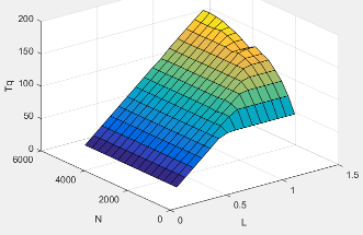
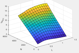
The inner torque lookup table, , is a function of engine speed and engine load, , where:
is inner torque based on gross indicated mean effective pressure, in N·m.
L is engine load at arbitrary cam phaser angles, corrected for final steady-state cam phaser angles, dimensionless.
N is engine speed, in rpm.
Dependencies
To enable this parameter, for the Torque model parameter,
select Torque Structure.
The friction torque lookup table, , is a function of engine speed and engine load, , where:
is friction torque offset to inner torque, in N·m.
L is engine load at arbitrary cam phaser angles, corrected for final steady-state cam phaser angles, dimensionless.
N is engine speed, in rpm.
Dependencies
To enable this parameter, for the Torque model parameter,
select Torque Structure.
Engine temperature modifier on friction torque, ƒfric,temp, dimensionless.
Dependencies
To enable this parameter, for the Torque model parameter,
select Torque Structure.
Engine temperature modifier breakpoints, in K.
Dependencies
To enable this parameter, for the Torque model parameter,
select Torque Structure.
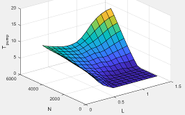
The pumping torque lookup
table, ƒTpump, is a function of engine load and engine
speed,
Tpump=ƒTpump(L,N), where:
Tpump is pumping torque, in N·m.
L is engine load, as a normalized cylinder air mass, dimensionless.
N is engine speed, in rpm.
Dependencies
To enable this parameter, for the Torque model parameter,
select Torque Structure.
The optimal spark lookup table, , is a function of engine speed and engine load, , where:
SAopt is optimal spark advance timing for maximum inner torque at stoichiometric air-fuel ratio (AFR), in deg.
L is engine load at arbitrary cam phaser angles, corrected for final steady-state cam phaser angles, dimensionless.
N is engine speed, in rpm.

Dependencies
To enable this parameter, for the Torque model parameter,
select Torque Structure.
Inner torque load breakpoints, dimensionless.
Dependencies
To enable this parameter, for the Torque model parameter,
select Torque Structure.
Inner torque speed breakpoints, in rpm.
Dependencies
To enable this parameter, for the Torque model parameter,
select Torque Structure.
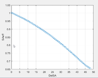
The spark efficiency lookup table, , is a function of the spark retard from optimal
where:
is the spark retard efficiency multiplier, dimensionless.
is the spark retard timing distance from optimal spark advance, in deg.
Dependencies
To enable this parameter, for the Torque model parameter,
select Torque Structure.
Spark retard from optimal inner torque timing breakpoints, in deg.
Dependencies
To enable this parameter, for the Torque model parameter,
select Torque Structure.
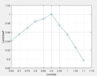
The lambda efficiency lookup table, , is a function of lambda, , where:
is the lambda multiplier on inner torque to account for the air-fuel ratio (AFR) effect, dimensionless.
is lambda, AFR normalized to stoichiometric fuel AFR, dimensionless.
Dependencies
To enable this parameter, for the Torque model parameter,
select Torque Structure.
Lambda effect on inner torque lambda breakpoints, dimensionless.
Dependencies
To enable this parameter, for the Torque model parameter,
select Torque Structure.
Exhaust
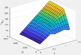
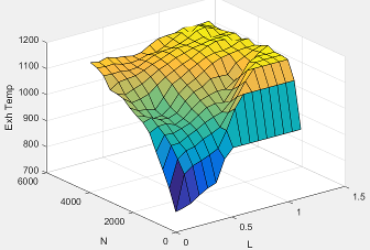
The exhaust temperature lookup table, , is a function of engine load and engine speed
where:
Texh is engine exhaust temperature, in K.
L is normalized cylinder air mass or engine load, dimensionless.
N is engine speed, in rpm.
Engine load breakpoints used for exhaust temperature lookup table, dimensionless.
Engine speed breakpoints used for exhaust temperature lookup table, in rpm.
Exhaust gas-specific heat, , in J/(kg·K).
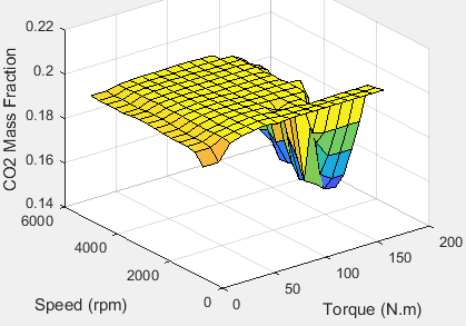
The SI Core Engine CO2 emission mass fraction lookup table is a function of engine torque and engine speed, CO2 Mass Fraction = ƒ(Speed, Torque), where:
CO2 Mass Fraction is the CO2 emission mass fraction, dimensionless.
Speed is engine speed, in rpm.
Torque is engine torque, in N·m.
Dependencies
To enable this parameter, on the Exhaust tab, select CO2.
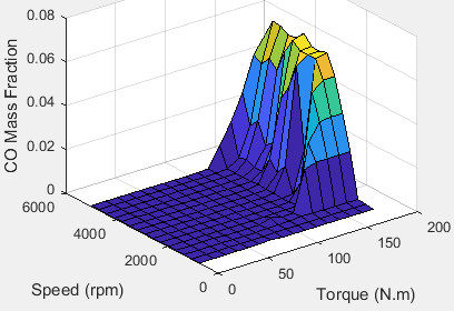
The SI Core Engine CO emission mass fraction lookup table is a function of engine torque and engine speed, CO Mass Fraction = ƒ(Speed, Torque), where:
CO Mass Fraction is the CO emission mass fraction, dimensionless.
Speed is engine speed, in rpm.
Torque is engine torque, in N·m.
Dependencies
To enable this parameter, on the Exhaust tab, select CO.
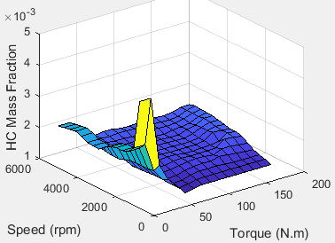
The SI Core Engine HC emission mass fraction lookup table is a function of engine torque and engine speed, HC Mass Fraction = ƒ(Speed, Torque), where:
HC Mass Fraction is the HC emission mass fraction, dimensionless.
Speed is engine speed, in rpm.
Torque is engine torque, in N·m.
Dependencies
To enable this parameter, on the Exhaust tab, select HC.
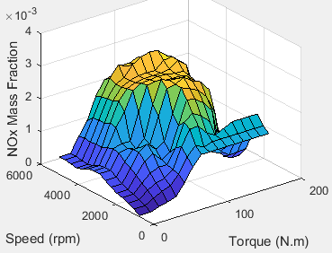
The SI Core Engine NOx emission mass fraction lookup table is a function of engine torque and engine speed, NOx Mass Fraction = ƒ(Speed, Torque), where:
NOx Mass Fraction is the NOx emission mass fraction, dimensionless.
Speed is engine speed, in rpm.
Torque is engine torque, in N·m.
Dependencies
To enable this parameter, on the Exhaust tab, select NOx.
The SI Core Engine PM emission mass fraction lookup table is a function of engine torque and engine speed where:
PM is the PM emission mass fraction, dimensionless.
Speed is engine speed, in rpm.
Torque is engine torque, in N·m.
Dependencies
To enable this parameter, on the Exhaust tab, select PM.
Engine speed breakpoints used for the emission mass fractions lookup tables, in rpm.
Dependencies
To enable this parameter, on the Exhaust tab, select CO2, CO, NOx, HC, or PM.
Engine torque breakpoints used for the emission mass fractions lookup tables, in N·m.
Dependencies
To enable this parameter, on the Exhaust tab, select CO2, CO, NOx, HC, or PM.
Fuel
Fuel injector slope, , mg/ms.
Air-fuel ratio, .
Fuel lower heating value, LHV, in J/kg.
Specific gravity of fuel, Sgfuel, dimensionless.
References
[1] Gerhardt, J., Hönninger, H., and Bischof, H., A New Approach to Functional and Software Structure for Engine Management Systems — BOSCH ME7. SAE Technical Paper 980801, 1998.
[2] Heywood, John B. Internal Combustion Engine Fundamentals. New York: McGraw-Hill, 1988.
Extended Capabilities
Version History
Introduced in R2017a