Main Content

Interior PM Controller

Torque-based, field-oriented controller for an internal permanent magnet synchronous motor

  • Interior PM Controller block

Libraries:
Powertrain Blockset / Propulsion / Electric Motor Controllers

Description

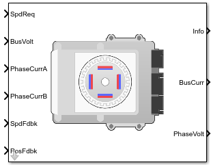
The Interior PM Controller block implements a torque-based, field-oriented controller for an internal permanent magnet synchronous motor (PMSM) with an optional outer-loop speed controller. The internal torque control implements strategies for achieving maximum torque per ampere (MTPA) and weakening the magnetic flux. You can specify either the speed or torque control type.

The Interior PM Controller implements equations for speed control, torque determination, regulators, transforms, and motors.

The figure illustrates the information flow in the block.

The block implements equations that use these variables.

ω

Rotor speed

ω*

Rotor speed command

T*

Torque command

id

i*d

d-axis current

d-axis current command

iq

i*q

q-axis current

q-axis current command

vd,

v*d

d-axis voltage

d-axis voltage command

vq

v*q

q-axis voltage

q-axis voltage command

va, vb, vc

Stator phase a, b, c voltages

ia, ib, ic

Stator phase a, b, c currents

Speed Controller

To implement the speed controller, select the Control Type parameter Speed Control. If you select the Control Type parameter Torque Control, the block does not implement the speed controller.

The speed controller determines the torque command by implementing a state filter, and calculating the feedforward and feedback commands. If you do not implement the speed controller, input a torque command to the Interior PM Controller block.

State Filter

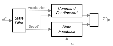
The state filter is a low-pass filter that generates the acceleration command based on the speed command. On the Speed Controller tab:

  • To make the speed-command lag time negligible, specify a Bandwidth of the state filter parameter.

  • To calculate a Speed regulation time constant, Ksf gain based on the state filter bandwidth, select Calculate Speed Regulator Gains.

The discrete form of characteristic equation is given by:

z+KsfTsm1

The filter calculates the gain using this equation.

Ksf=1exp(Tsm2πEVsf)Tsm

The equations use these variables.

EVsf

Bandwidth of the speed command filter

Tsm

Motion controller sample time

Ksf

Speed regulator time constant

State Feedback

To generate the state feedback torque, the block uses the filtered speed error signal from the state filter. The feedback torque calculation also requires gains for speed regulator.

On the Speed Controller tab, select Calculate Speed Regulator Gains to calculate:

  • Proportional gain, ba

  • Angular gain, Ksa

  • Rotational gain, Kisa

For the gain calculations, the block uses the inertia from the Physical inertia, viscous damping, static friction parameter value on the Motor Parameters tab.

The gains for the state feedback are calculated using these equations.

CalculationEquations
Discrete forms of characteristic equation

z3+(3Jp+Tsba+ Ts2Ksa+Ts3Kisa)Jpz2+(3Jp 2Tsba Ts2Ksa)Jpz+Jp+TsbaJp

(zp1)(zp2)(zp3)=z3+(p1+p2+p3)z2+(p1p2+p2p3+p13)z2p1p2p3

Speed regulator proportional gain

ba=JpJpp1p2p3Tsm

Speed regulator integral gain

Ksa=Jp(p1p2+p2p3+p3p1)3Jp+2baTsmTsm2

Speed regulator double integral gain

Kisa=Jp(p1+p2+p3)+3JpbaTsmKsaTsm2Tsm3

The equations use these variables.

P

Motor pole pairs

ba

Speed regulator proportional gain

Ksa

Speed regulator integral gain

Kisa

Speed regulator double integral gain

Jp

Motor inertia

Tsm

Motion controller sample time

Command Feedforward

To generate the state feedforward torque, the block uses the filtered speed and acceleration from the state filter. Also, the feedforward torque calculation uses the inertia, viscous damping, and static friction. To achieve zero tracking error, the torque command is the sum of the feedforward and feedback torque commands.

Selecting Calculate Speed Regulator Gains on the Speed Controller tab updates the inertia, viscous damping, and static friction with the Physical inertia, viscous damping, static friction parameter values on the Motor Parameters tab.

The feedforward torque command uses this equation.

Tcmd_ff= Jpω˙m+Fvωm+Fs ωm|ωm|

where:

Jp

Motor inertia

Tcmd_ff

Torque command feedforward

Fs

Static friction torque constant

Fv

Viscous friction torque constant

Fs

Static friction torque constant

ωm

Rotor speed

Torque Determination

The block uses a maximum torque per ampere (MTPA) trajectory to calculate the base speed and the current commands. The available bus voltage determines the base speed. The direct (d) and quadrature (q) permanent magnet (PM) determines the induced voltage.

CalculationEquations
Electrical base speed transition into field weakeningωbase=  vmax(Lqiq)2+(Ldid+ λpm)2
d-axis voltagevd=ωeLqiqmax
q-axis voltagevq=ωe(Ldid_max+ λpm)
Maximum phase currentimax2=id_max2+iq_max2
Maximum line to neutral voltagevmax= vbus 3
d-axis phase current MTPA tableIm=2Tmax3Pλpmid_mtpa=λpm4(LqLd)λpm216(LqLd)2+Im22
q-axis phase current MTPA tableiq_mtpa=Im2(imtpa)2
Torque MTPA breakpointsTmtpa= 32P(λpmiq+(Ld Lq)idiq)
Field weakening, using the speed-based voltage limits

(Lqiq)2+(Ldid+ λpm)2 vmax2ωe2

iq= imax2 id2

(Ld2 Lq2)id2+2λpmLdid+ λpm+ Lq2imax2vmax2ωe2=0

idfw= λpmLd+ (λpmLd)2 (Ld2 Lq2)(λpm2+  Lq2imax2 vmax2ωe2  )(Ld2 Lq2)

Tfw= 32P(λpmiqfw+(Ld Lq)idfwiqfw)

Current command
If|ωe| ωbase
		idref= idmtpa(Tref)iqref= iqmtpa(Tref)
Else
		 idfw= max(idfw, imax)iqfw= imax2 id2		
		If  Tfw<Tref
			idref= idfwiqref= iqfw
		Else
			idref= idfwiqref= Tref32P(λpm+(Ld Lq)idfw)
		End
End

The equations use these variables.

imax

Maximum phase current

id

d-axis current

iq

q-axis current

id_max

Maximum d-axis phase current

iq_max

Maximum q-axis phase current

id_mtpa

d-axis phase current MTPA table

iq_mtpa

q-axis phase current MTPA table

Im

Estimated maximum current

idfw

d-axis field weakening current

iqfw

q-axis field weakening current

ωe

Rotor electrical speed

λpm

Permanent magnet flux linkage

vd

d-axis voltage

vq

q-axis voltage

vmax

Maximum line to neutral voltage

vbus

DC bus voltage

Ld

d-axis winding inductance

Lq

q-axis winding inductance

P

Motor pole pairs

Tfw

Field weakening torque

Tmtpa

Torque MTPA breakpoints

Current Regulators

The block regulates the current with an anti-windup feature. Classic proportional-integrator (PI) current regulators do not consider the d-axis and q-axis coupling or the back-electromagnetic force (EMF) coupling. As a result, transient performance deteriorates. To account for the coupling, the block implements the complex vector current regulator (CVCR) in the scalar format of the rotor reference frame. The CVCR decouples:

  • d-axis and q-axis current cross-coupling

  • Back-EMF cross-coupling

The current frequency response is a first-order system, with a bandwidth of EVcurrent.

The block implements these equations.

CalculationEquations
Motor voltage, in the rotor reference frameLddiddt= vdRsid+pωmLqiqLqdiqdt= vqRsiqpωmLdidpωmλpm
Current regulator gainsωb=2πEVcurrentKp_d=LdωbKp_q=LqωbKi=Rsωb
Transfer functionsididref= ωbs+ωbiqiqref= ωbs+ωb

The equations use these variables.

EVcurrent

Current regulator bandwidth

id

d-axis current

iq

q-axis current

Kp_d

Current regulator d-axis gain

Kp_q

Current regulator q-axis gain

Ld

d-axis winding inductance

Lq

q-axis winding inductance

Rs

Stator phase winding resistance

ωm

Rotor speed

vd

d-axis voltage

vq

q-axis voltage

λpm

Permanent magnet flux linkage

P

Motor pole pairs

Transforms

To calculate the voltages and currents in balanced three-phase (a, b) quantities, quadrature two-phase (α, β) quantities, and rotating (d, q) reference frames, the block uses the Clarke and Park Transforms.

In the transform equations.

ωe=Pωmdθedt= ωe

TransformDescriptionEquations

Clarke

Converts balanced three-phase quantities (a, b) into balanced two-phase quadrature quantities (α, β).

xα= 23xa 13xb 13xcxβ= 32xb 32xc

Park

Converts balanced two-phase orthogonal stationary quantities (α, β) into an orthogonal rotating reference frame (d, q).

xd= xαcosθe+ xβsinθexq= xαsinθe+ xβcosθe

Inverse Clarke

Converts balanced two-phase quadrature quantities (α, β) into balanced three-phase quantities (a, b).

xa= xaxb= 12xα+ 32xβxc= 12xα 32xβ

Inverse Park

Converts an orthogonal rotating reference frame (d, q) into balanced two-phase orthogonal stationary quantities (α, β).

xα= xdcosθe xqsinθexβ= xdsinθe+ xqcosθe

The transforms use these variables.

ωm

Rotor speed

P

Motor pole pairs

ωe

Rotor electrical speed

Θe

Rotor electrical angle

x

Phase current or voltage

Motor

The block uses the phase currents and phase voltages to estimate the DC bus current. Positive current indicates battery discharge. Negative current indicates battery charge. The block uses these equations.

Load power

LdPwr=va ia+ vb ib+ vc ic

Source power

SrcPwr= LdPwr+PwrLoss

DC bus current

ibus= SrcPwrvbus

Estimated rotor torque

MtrTrqest=1.5P[λiq+(LdLq)idiq]

Power loss for single efficiency source to load

PwrLoss=100EffEffLdPwr

Power loss for single efficiency load to source

PwrLoss=100Eff100|LdPwr|

Power loss for tabulated efficiency

PwrLoss= f(ωm,MtrTrqest)

The equations use these variables.

va, vb, vc

Stator phase a, b, c voltages

vbus

Estimated DC bus voltage

ia, ib, ic

Stator phase a, b, c currents

ibus

Estimated DC bus current

Eff

Overall inverter efficiency

ωm

Rotor mechanical speed

Lq

q-axis winding inductance

Ld

d-axis winding inductance

iq

q-axis current

id

d-axis current

λ

Permanent magnet flux linkage

P

Motor pole pairs

Electrical Losses

To specify the electrical losses, on the Electrical Losses tab, for Parameterize losses by, select one of these options.

SettingBlock Implementation
Single efficiency measurement

Electrical loss calculated using a constant value for inverter efficiency.

Tabulated loss data

Electrical loss calculated as a function of motor speeds and load torques.

Tabulated efficiency data

Electrical loss calculated using inverter efficiency that is a function of motor speeds and load torques.

  • Converts the efficiency values you provide into losses and uses the tabulated losses for simulation.

  • Ignores efficiency values you provide for zero speed or zero torque. Losses are assumed zero when either torque or speed is zero.

  • Uses linear interpolation to determine losses. Provide tabulated data for low speeds and low torques, as required, to get the desired level of accuracy for lower power conditions.

  • Does not extrapolate loss values for speed and torque magnitudes that exceed the range of the table.

For best practice, use Tabulated loss data instead of Tabulated efficiency data:

  • Efficiency becomes ill defined for zero speed or zero torque.

  • You can account for fixed losses that are still present for zero speed or torque.

Ports

Input

expand all

Rotor speed command, ω*m, in rad/s.

Dependencies

To create this port, select Speed Control for the Control Type parameter.

Torque command, T*, in N·m.

Dependencies

To create this port, select Torque Control for the Control Type parameter.

DC bus voltage, vbus, in V.

Stator current phase a, ia, in A.

Stator current phase b, ib, in A.

Rotor speed, ωm, in rad/s.

Rotor electrical angle, Θm, in rad.

Output

expand all

Bus signal containing these block calculations.

SignalDescriptionUnits

SrcPwr

Source power

W

LdPwr

Load power

W

PwrLoss

Power loss

W

MtrTrqEst

Estimated motor torque

N·m

Estimated DC bus current, ibus, in A.

Stator terminal voltages, Va, Vb, and Vc, in V.

Parameters

expand all

Block Options

If you select Torque Control, the block does not implement the speed controller.

This table summarizes the port configurations.

Port ConfigurationCreates Ports
Speed Control

SpdReq

Torque Control

TrqCmd

Motor Parameters

Stator phase winding resistance, Rs, in ohm.

Dependencies

This table summarizes the parameter dependencies.

ParameterUsed to Derive
ParameterTab

Stator resistance, Rs

D and Q axis integral gain, Ki

Current Controller

D-axis winding inductance, Ld, in H.

Dependencies

This table summarizes the parameter dependencies.

ParameterUsed to Derive
ParameterTab

D-axis inductance, Ld

Torque Breakpoints, T_mtpa

D-axis table data, id_mtpa

Q-axis table data, iq_mtpa

D, q, and max current limits, idq_limits

Id and Iq Calculation

Q-axis winding inductance, Lq, in H.

Dependencies

This table summarizes the parameter dependencies.

ParameterUsed to Derive
ParameterTab

Q-axis inductance, Lq

Torque Breakpoints, T_mtpa

D-axis table data, id_mtpa

Q-axis table data, iq_mtpa

D, Q, and max current limits, idq_limits

Id and Iq Calculation

Permanent magnet flux, λpm, in Wb.

Dependencies

This table summarizes the parameter dependencies.

ParameterUsed to Derive
ParameterTab

Permanent magnet flux, lambda_pm

Torque Breakpoints, T_mtpa

D-axis table data, id_mtpa

Q-axis table data, iq_mtpa

D, Q, and max current limits, idq_limits

Id and Iq Calculation

Motor pole pairs, P.

Dependencies

This table summarizes the parameter dependencies.

ParameterUsed to Derive
ParameterTab

Number of pole pairs, PolePairs

Torque Breakpoints, T_mtpa

D-axis table data, id_mtpa

Q-axis table data, iq_mtpa

D, Q, and max current limits, idq_limits

Id and Iq Calculation

Mechanical properties of the motor:

  • Motor inertia, Fv, in kgm^2

  • Viscous friction torque constant, Fv, in N·m/(rad/s)

  • Static friction torque constant, Fs, in N·m

Dependencies

To enable this parameter, set the Control Type parameter to Speed Control.

For the gain calculations, the block uses the inertia from the Physical inertia, viscous damping, static friction parameter value that is on the Motor Parameters tab.

This table summarizes the parameter dependencies.

ParameterUsed to Derive
ParameterTab

Physical inertia, viscous damping, static friction, Mechanical

Proportional gain, ba

Angular gain, Ksa

Rotational gain, Kisa

Inertia compensation, Jcomp

Viscous damping compensation, Fv

Static friction, Fs

Speed Controller
Id and Iq Calculation

Motor constraint for MTPA control.

Maximum current, in A.

Dependencies

To enable this parameter, set Motor constraint to Maximum Current.

This table summarizes the parameter dependencies.

ParameterUsed to Derive
ParameterTab

Maximum torque, T_max

Torque Breakpoints, T_mtpa

D-axis table data, id_mtpa

Q-axis table data, iq_mtpa

D, Q, and max current limits, idq_limits

Id and Iq Calculation

Maximum torque, in N·m.

Dependencies

To enable this parameter, set Motor constraint to Maximum Torque.

This table summarizes the parameter dependencies.

ParameterUsed to Derive
ParameterTab

Maximum torque, T_max

Torque Breakpoints, T_mtpa

D-axis table data, id_mtpa

Q-axis table data, iq_mtpa

D, Q, and max current limits, idq_limits

Id and Iq Calculation

Dependencies

This table summarizes the parameter dependencies.

ParameterUsed to Derive
ParameterTab

MTPA table breakpoints, pb

Torque Breakpoints, T_mtpa

D-axis table data, id_mtpa

Q-axis table data, iq_mtpa

D, Q, and max current limits, idq_limits

Id and Iq Calculation

Click to derive parameters.

Dependencies

On the Id and Iq Calculation tab, when you select Calculate MPTA Table data, the block calculates derived parameters. The table summarizes the derived parameter dependencies on other block parameters.

Derived Parameter on Id and Iq Calculation tabDepends On
ParameterTab

Torque Breakpoints, T_mtpa

Tmtpa= 32P(λpmiq+(Ld Lq)idiq)

Maximum torque, T_max

MTPA table breakpoints, pb

Id and Iq Calculation

D-axis table data, id_mtpa

Im=2Tmax3Pλpmid_mtpa=λpm4(LqLd)λpm216(LqLd)2+Im22

Permanent magnet flux, lambda_pm

D-axis inductance, Ld

Q-axis inductance, Lq

Number of pole pairs, PolePairs

Motor Parameters

Q-axis table data, iq_mtpa

iq_mtpa=Im2(imtpa)2

D, Q, and max current limits, idq_limits

The equations use these variables.

imax

Maximum phase current

id

d-axis current

iq

q-axis current

id_max

Maximum d-axis phase current

iq_max

Maximum q-axis phase current

id_mtpa

d-axis phase current MTPA table

iq_mtpa

q-axis phase current MTPA table

λpm

Permanent magnet flux linkage

Ld

d-axis winding inductance

Lq

q-axis winding inductance

P

Motor pole pairs

Tmtpa

Torque MTPA breakpoints

Im

Estimated maximum current

Derived torque breakpoints, in N·m.

Dependencies

This table summarizes the parameter dependencies.

ParameterDependency
ParameterTab

Torque Breakpoints, T_mtpa

Maximum torque, T_max

MTPA table breakpoints, pb

Id and Iq Calculation

Permanent magnet flux, lambda_pm

D-axis inductance, Ld

Q-axis inductance, Lq

Number of pole pairs, PolePairs

Motor Parameters

Derived d-axis table data, in A.

Dependencies

This table summarizes the parameter dependencies.

ParameterDependency
ParameterTab

D-axis table data, id_mtpa

Maximum torque, T_max

MTPA table breakpoints, pb

Id and Iq Calculation

Permanent magnet flux, lambda_pm

D-axis inductance, Ld

Q-axis inductance, Lq

Number of pole pairs, PolePairs

Motor Parameters

Derived q-axis table data, in A.

Dependencies

This table summarizes the parameter dependencies.

ParameterDependency
ParameterTab

D-axis table data, id_mtpa

Maximum torque, T_max

MTPA table breakpoints, pb

Id and Iq Calculation

Permanent magnet flux, lambda_pm

D-axis inductance, Ld

Q-axis inductance, Lq

Number of pole pairs, PolePairs

Motor Parameters

Derived d, q, and maximum current limits, in A.

Dependencies

This table summarizes the parameter dependencies.

ParameterDependency
ParameterTab

D, Q, and max current limits, idq_limits

Maximum torque, T_max

MTPA table breakpoints, pb

Id and Iq Calculation

Permanent magnet flux, lambda_pm

D-axis inductance, Ld

Q-axis inductance, Lq

Number of pole pairs, PolePairs

Motor Parameters

Current Controller

Derived current regulator bandwidth, in Hz.

Dependencies

This table summarizes the parameter dependencies.

ParameterUsed to Derive
ParameterTab

Bandwidth of the current regulator, EV_current

D-axis proportional gain, Kp_d

Q-axis proportional gain, Kp_q

D and Q axis proportional gain, Ki

Current Controller

Derived torque control sample time, in s.

Dependencies

This table summarizes the parameter dependencies.

ParameterUsed to Derive
ParameterTab

Sample time for the torque control, Tst

Speed regulation time constant, Ksf

Speed Controller

Click to derive parameters.

Dependencies

On the Current Controller tab, when you select Calculate Current Regulator Gains, the block calculates derived parameters. The table summarizes the derived parameter dependencies on other block parameters.

Derived Parameter on Current Controller tabDependency
ParameterTab

D-axis proportional gain, Kp_d

Q-axis proportional gain, Kp_q

D and Q axis integral gain, Ki

Bandwidth of the current regulator, EV_current

Current Controller

Stator resistance, Rs

Motor Parameters

Derived d-axis proportional gain, in V/A.

Dependencies

This table summarizes the parameter dependencies.

ParameterDependency
ParameterTab

D-axis proportional gain, Kp_d

Bandwidth of the current regulator, EV_current

Current Controller

Derived q-axis proportional gain, in V/A.

Dependencies

This table summarizes the parameter dependencies.

ParameterDependency
ParameterTab

Q-axis proportional gain, Kp_q

Bandwidth of the current regulator, EV_current

Current Controller

Derived d- and q- axis integral gains, in V/A·s.

Dependencies

This table summarizes the parameter dependencies.

ParameterDependency
ParameterTab

D and Q axis integral gain, Ki

Stator resistance, Rs

Motor Parameters

Speed Controller

Motion controller bandwidth, in Hz. Set the first element of the vector to the desired cutoff frequency. Set the second and third elements of the vector to the higher-order cut off frequencies. You can set the value of the next element to 1/5 the value of the previous element. For example, if the desired cutoff frequency is 20 Hz, specify [20 4 0.8].

Dependencies

The parameter is enabled when the Control Type parameter is set to Speed Control.

ParameterUsed to Derive
ParameterTab

Bandwidth of the motion controller, EV_motion

Proportional gain, ba

Angular gain, Ksa

Rotational gain, Kisa

Speed Controller

State filter bandwidth, in Hz.

Dependencies

The parameter is enabled when the Control Type parameter is set to Speed Control.

ParameterUsed to Derive
ParameterTab

Bandwidth of the state filter, EV_sf

Speed regulation time constant, Ksf

Speed Controller

Click to derive parameters.

Dependencies

On the Speed Controller tab, when you select Calculate Speed Regulator Gains, the block calculates derived parameters. The table summarizes the derived parameters that depend on other block parameters.

Derived Parameter on Speed Controller tabDepends On
ParameterTab

Proportional gain, ba

ba=JpJpp1p2p3Tsm

Bandwidth of the motion controller, EV_motion

Bandwidth of the state filter, EV_sf

Speed Controller

Angular gain, Ksa

Ksa=Jp(p1p2+p2p3+p3p1)3Jp+2baTsmTsm2

Sample time for the torque control, Tst

Current Controller

Rotational gain, Kisa

Kisa=Jp(p1+p2+p3)+3JpbaTsmKsaTsm2Tsm3Physical inertia, viscous damping, static friction, Mechanical

Motor Parameters

Speed regulation time constant, Ksf

Ksf=1exp(Tsm2πEVsf)Tsm

Inertia compensation, Jcomp

Jcomp = JpPhysical inertia, viscous damping, static friction, Mechanical

Motor Parameters

Viscous damping compensation, Fv

Fv

Static friction, Fs

Fs

The equations use these variables.

P

Motor pole pairs

ba

Speed regulator proportional gain

Ksa

Speed regulator integral gain

Kisa

Speed regulator double integral gain

Ksf

Speed regulator time constant

Jp

Motor inertia

EVsf

State filter bandwidth

EVmotion

Motion controller bandwidth

Derived proportional gain, in N·m/(rad/s).

Dependencies

This table summarizes the parameter dependencies.

ParameterDependency
ParameterTab

Proportional gain, ba

Physical inertia, viscous damping, static friction, Mechanical

Motor Parameters

Bandwidth of the motion controller, EV_motion

Speed Controller

Derived angular gain, in N·m/rad.

Dependencies

This table summarizes the parameter dependencies.

ParameterDependency
ParameterTab

Angular gain, Ksa

Physical inertia, viscous damping, static friction, Mechanical

Motor Parameters

Bandwidth of the motion controller, EV_motion

Speed Controller

Derived rotational gain, in N·m/(rad*s).

Dependencies

This table summarizes the parameter dependencies.

ParameterDependency
ParameterTab

Rotational gain, Kisa

Physical inertia, viscous damping, static friction, Mechanical

Motor Parameters

Bandwidth of the motion controller, EV_motion

Speed Controller

Derived speed regulation time constant, in 1/s.

Dependencies

This table summarizes the parameter dependencies.

ParameterDependency
ParameterTab

Speed regulation time constant, Ksf

Sample time for the torque control, Tst

Current Controller

Bandwidth of the state filter, EV_sf

Speed Controller

Derived inertia compensation, in kg·m^2.

Dependencies

This table summarizes the parameter dependencies.

ParameterDependency
ParameterTab

Inertia compensation, Jcomp

Physical inertia, viscous damping, static friction, Mechanical

Motor Parameters

Dependencies

This table summarizes the parameter dependencies.

ParameterDependency
ParameterTab

Viscous damping compensation, Fv

Physical inertia, viscous damping, static friction, Mechanical

Motor Parameters

Derived static friction, in N·m/(rad/s).

Dependencies

This table summarizes the parameter dependencies.

ParameterDependency
ParameterTab

Static friction, Fs

Physical inertia, viscous damping, static friction, Mechanical

Motor Parameters
Electrical Losses

SettingBlock Implementation
Single efficiency measurement

Electrical loss calculated using a constant value for inverter efficiency.

Tabulated loss data

Electrical loss calculated as a function of motor speeds and load torques.

Tabulated efficiency data

Electrical loss calculated using inverter efficiency that is a function of motor speeds and load torques.

  • Converts the efficiency values you provide into losses and uses the tabulated losses for simulation.

  • Ignores efficiency values you provide for zero speed or zero torque. Losses are assumed zero when either torque or speed is zero.

  • Uses linear interpolation to determine losses. Provide tabulated data for low speeds and low torques, as required, to get the desired level of accuracy for lower power conditions.

  • Does not extrapolate loss values for speed and torque magnitudes that exceed the range of the table.

For best practice, use Tabulated loss data instead of Tabulated efficiency data:

  • Efficiency becomes ill defined for zero speed or zero torque.

  • You can account for fixed losses that are still present for zero speed or torque.

Overall inverter efficiency, Eff, in %.

Dependencies

To enable this parameter, for Parameterize losses by, select Tabulated loss data.

Speed breakpoints for lookup table when calculating losses, in rad/s.

Dependencies

To enable this parameter, for Parameterize losses by, select Tabulated loss data.

Torque breakpoints for lookup table when calculating losses, in N·m.

Dependencies

To enable this parameter, for Parameterize losses by, select Tabulated loss data.

Array of values for electrical losses as a function of M speeds and N torques, in W. Each value specifies the losses for a specific combination of speed and torque. The matrix size must match the dimensions defined by the speed and torque vectors.

Dependencies

To enable this parameter, for Parameterize losses by, select Tabulated loss data.

Speed breakpoints for lookup table when calculating efficiency, in rad/s.

Dependencies

To enable this parameter, for Parameterize losses by, select Tabulated efficiency data.

Torque breakpoints for lookup table when calculating efficiency, in N·m.

Dependencies

To enable this parameter, for Parameterize losses by, select Tabulated efficiency data.

Array of efficiency as a function of M speeds and N torque, in %. Each value specifies the efficiency for a specific combination of speed and torque. The matrix size must match the dimensions defined by the speed and torque vectors.

The block ignores efficiency values for zero speed or zero torque. Losses are zero when either torque or speed is zero. The block uses linear interpolation.

To get the desired level of accuracy for lower power conditions, you can provide tabulated data for low speeds and low torques.

Dependencies

To enable this parameter, for Parameterize losses by, select Tabulated efficiency data.

References

[1] Lorenz, Robert D., Thomas Lipo, and Donald W. Novotny. “Motion control with induction motors.” Proceedings of the IEEE®, Vol. 82, Issue 8, August 1994, pp. 1215–1240.

[2] Morimoto, Shigeo, Masayuka Sanada, and Yoji Takeda. “Wide-speed operation of interior permanent magnet synchronous motors with high-performance current regulator.” IEEE Transactions on Industry Applications, Vol. 30, Issue 4, July/August 1994, pp. 920–926.

[3] Li, Muyang. “Flux-Weakening Control for Permanent-Magnet Synchronous Motors Based on Z-Source Inverters.” Master’s Thesis, Marquette University, e-Publications@Marquette, Fall 2014.

[4] Briz, Fernando, Michael W. Degner, and Robert D. Lorenz. "Analysis and design of current regulators using complex vectors." IEEE Transactions on Industry Applications, Vol. 36, Issue 3, May/June 2000, pp. 817–825.

[5] Briz, Fernando, et al. "Current and flux regulation in field-weakening operation [of induction motors]."IEEE Transactions on Industry Applications, Vol. 37, Issue 1, Jan/Feb 2001, pp. 42–50.

Extended Capabilities

C/C++ Code Generation
Generate C and C++ code using Simulink® Coder™.

Version History

Introduced in R2017a