802.11ax Feedback Status Misdetection Simulation for Uplink Trigger-Based Feedback NDP
This example shows how to measure the probability of misdetecting feedback status information in an uplink high efficiency (HE) trigger-based (TB) feedback null data packet (NDP) transmission from multiple uplink stations (STAs).
Introduction
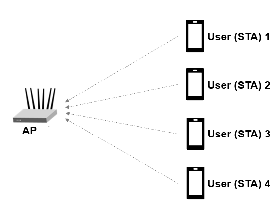
The 802.11ax [1] HE TB feedback NDP is a variant of the HE TB physical layer protocol data unit (PPDU). The HE TB feedback NDP transmission is controlled entirely by an access point (AP). All the parameters required for the transmission are provided in a trigger frame of type NDP feedback report poll (NFRP) sent to all STAs participating in the HE TB feedback transmission. Following the transmission of an NFRP trigger frame from the AP, multiple STAs may simultaneously transmit an HE TB feedback NDP, which carries the resource request information (feedback status) as shown in this diagram. For more information on the NDP feedback report procedure, see the NDP Feedback Report Procedure section of the wlanHETBConfig reference page.
This example measures the probability of misdetecting feedback status information for an HE TB feedback NDP by comparing the transmitted and received feedback statuses. A misdetection is recorded when the recovered feedback status is incorrect or undetermined. The example performs this measurement for a transmission between four STAs and an AP by using an end-to-end simulation. The STA infers the transmission parameters from the User Info field of the soliciting NFRP trigger frame. At each signal-to-noise ratio (SNR) point the STA transmits multiple packets with no impairments apart from multipath fading and noise. The STA demodulates the packet and recovers the feedback status. The AP determines the probability of misdetecting feedback status by comparing the recovered and transmitted feedback status.
Each STA transmits a waveform by performing these processing steps.
Determine if the STA is scheduled to transmit an HE TB feedback NDP.
Determine the RU tone set index and starting space time stream number for all transmitting STAs.
Generate an HE TB feedback NDP for the STAs.
Pass the waveform for each STA through an indoor channel by using the
wlanTGaxChannelSystem object (TM) . Model different channel realizations for each user and each packet by randomly varying the UserIndex property ofwlanTGaxChannel. This process results in the same spatial correlation properties for all STAs.Combine waveforms from all STAs.
Add additive white Gaussian noise (AWGN) to the received waveform. The AWGN creates the desired average SNR per subcarrier after orthogonal frequency-division multiplexing (OFDM) demodulation for each STA.
The receiver (AP) performs these processing steps on the received waveform.
Use perfect channel delay estimate to synchronize.
Extract the HE-LTF from the synchronized waveform and demodulate the HE-LTF.
Recover feedback status information from the demodulated HE-LTF symbols [2].
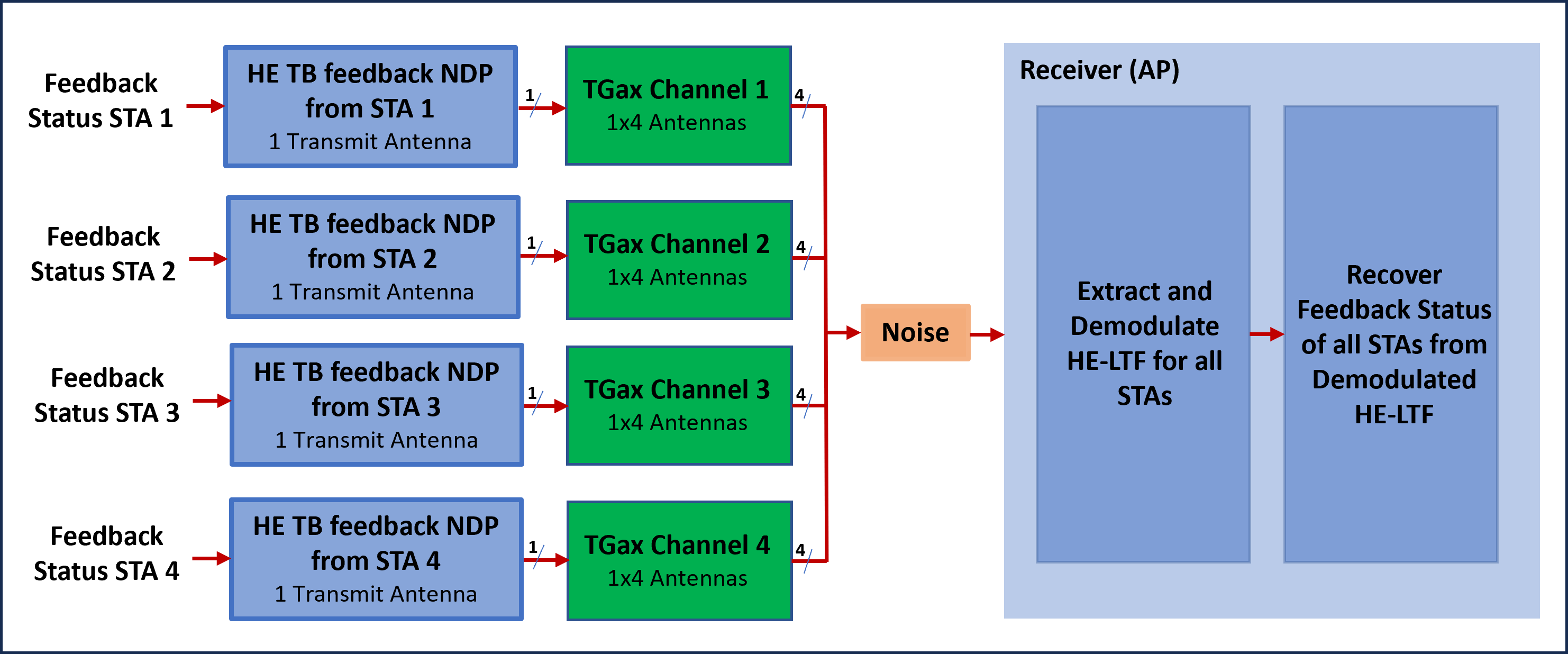
This figure shows the processing for each link between the STA and AP.
Simulate Uplink Transmission
This section simulates an end-to-end uplink scenario for multiple STAs and SNR points. Specify the number of STAs and the SNR range. This section estimates the probability of misdetecting feedback status for all STAs. The feedback status represents the resource request information from the STA and is defined in Table 26-3 of [1].
% Set transmission parameters numSTAs =4; % Number of uplink STAs STAID =
[1 19 2 4]; % STA association ID, assigned to each associated STA with an AP multiplexingFlag =
[0 1 0 0]; % Signaled in the trigger frame of type NFRP for each STA feedbackStatus =
[1 0 1 0]; % Resource request information signaled by each STA startingAID =
0; % Signaled in the trigger frame of type NFRP % Set simulation parameters numPackets =
50; % Number of packets to simulate snrRange =
-2:2:6; % SNR points (dB) chanBW =
'CBW20'; % Channel bandwidth numTx =
1; % Assume same number of transmit antennas for all STAs numRx =
4; % Number of receive (AP) antennas
HE TB Feedback NDP Waveform Configuration
Configure the waveform generator for each STA. The STA performs these steps.
Check if the STA is scheduled to transmit.
Calculate the RUToneSetIndex for each STA from
STAID,startingAID, andchanBW.Calculate starting space time stream number for all STAs from
STAID, startingAID,andchanBW.Generate configuration object for all STAs.
% Return the index of the transmitting STAs. Calculate RUToneSetIndex and starting space time stream for all STAs.
[txSTAIndex,ruToneSetIndexPerSTA,startingSTSNumPerSTA] = heTBNDPMappingParams(chanBW,numSTAs,multiplexingFlag,startingAID,STAID);
numTxSTAs = numel(txSTAIndex); % STAs scheduled to transmit
cfgSTA = cell(1,numTxSTAs);

% Generate the configuration object and set the feedback status property for all STAs
cfgBase = wlanHETBConfig('ChannelBandwidth',chanBW,'NumTransmitAntennas',numTx,'SpatialMapping','Fourier');
cfgNDP = getNDPFeedbackConfiguration(cfgBase);
if numSTAs~=numel(feedbackStatus)
    error('The number of elements in FeedbackStatus must be equal to the number of STAs');
end

for u=1:numTxSTAs
      cfgNDP.RUToneSetIndex = ruToneSetIndexPerSTA(u);
      cfgNDP.StartingSpaceTimeStream = startingSTSNumPerSTA(u);
      cfgNDP.FeedbackStatus = feedbackStatus(txSTAIndex(u));
      cfgSTA{u} = cfgNDP;
end
Channel Configuration
This example uses a TGax non-line-of-sight (NLOS) indoor channel model with delay profile Model-D. Model-D is considered NLOS when the distance between the transmitter and receiver is greater than or equal to ten meters. For more information, see wlanTGaxChannel. This example assumes that all STAs are at the same distance from the AP.
delayProfile ='Model-D'; % TGax channel multipath delay profile tgaxBase = wlanTGaxChannel; tgaxBase.DelayProfile = delayProfile; tgaxBase.SampleRate = wlanSampleRate(cfgSTA{1}); tgaxBase.TransmissionDirection = 'Uplink'; tgaxBase.TransmitReceiveDistance = 10; tgaxBase.ChannelBandwidth = chanBW; tgaxBase.NumReceiveAntennas = numRx; tgaxBase.NormalizeChannelOutputs = false; tgaxBase.PathGainsOutputPort = true;
Create an individual channel for each STA. Each channel is a clone of tgaxBase, but with a different UserIndex property, and is stored in cell array tgax. The UserIndex property of each individual channel creates a unique channel for each user. This example uses a random channel realization for each packet by randomly varying the UserIndex property of each transmitted packet.
% A cell array stores the channel objects, one per STA.
tgax = cell(1,numTxSTAs);
for u=1:numTxSTAs
    tgax{u} = clone(tgaxBase);
    tgax{u}.NumTransmitAntennas = numTx;
    tgax{u}.UserIndex = u;
end
chInfo = info(tgaxBase);
chFilterCoefficients = chInfo.ChannelFilterCoefficients; % Channel filter coefficients
Processing SNR Points
This section tests a number of packets at each SNR point and calculates the probability of misdetecting recovered feedback status.
To parallelize processing of the SNR points, you can use a parfor loop. To enable the use of parallel computing for increased speed comment out the 'for' statement and uncomment the 'parfor' statement below.
% Processing SNR Points
ofdmInfo = wlanHEOFDMInfo('HE-LTF',cfgNDP);
numSNR = numel(snrRange); % Number of SNR points
misdetectionProbability = zeros(numTxSTAs,numSNR);
ind = wlanFieldIndices(cfgNDP); % Same for all STAs

%parfor isnr=1:numSNR % Use 'parfor' to speed up the simulation
for isnr=1:numSNR
    % Set random substream index per iteration to ensure that each
    % iteration uses a repeatable set of random numbers
    stream = RandStream('combRecursive','Seed',0);
    stream.Substream = isnr;
    RandStream.setGlobalStream(stream);
    rxFeedbackStatus = zeros(numPackets,numTxSTAs);
    chDelay = zeros(1,numTxSTAs);

    for pktIdx=1:numPackets
        rxWaveform = 0;

        % Generate random channel realization for each packet by varying
        % the UserIndex property of the channel. This assumes all STAs
        % have the same number of transmit antennas.
        chPermutations = randperm(numTxSTAs);
        for u=1:numTxSTAs
            % Generate HE TB feedback NDP waveform for each STA
            txSTA = wlanWaveformGenerator([],cfgSTA{u});

            % Pass waveform through a random TGax Channel
            channelIdx = chPermutations(u);
            reset(tgax{channelIdx}); % New channel realization
            [rxSTA,h] = tgax{channelIdx}([txSTA; zeros(50,size(txSTA,2))]);

            % Perform perfect channel delay estimate to find the start of
            % the packet
            chDelay(u) = channelDelay(h,chFilterCoefficients);

            % Combine uplink waveform from all STAs into one waveform
            rxWaveform = rxWaveform+rxSTA;
        end

        % Synchronize later in time by using the maximum channel delay
        % between all channels as the start of the packet
        pktOffset = max(chDelay(u)); % Packet start index

        % Pass the waveform through AWGN channel. Account for noise
        % energy in unused subcarriers.
        snrVal = snrRange(isnr)-10*log10(ofdmInfo.FFTLength/ofdmInfo.NumTones);
        rxWaveform = awgn(rxWaveform,snrVal);

        % Uplink processing (at the AP)
        rxHELTF = rxWaveform(pktOffset+(ind.HELTF(1):ind.HELTF(2)),:);
        heltfDemod = wlanHEDemodulate(rxHELTF,'HE-LTF',chanBW,cfgNDP.GuardInterval,cfgNDP.HELTFType);

        % Recover feedback status for all STAs
        for u=1:numTxSTAs
            rxFeedbackStatus(pktIdx,u) = wlanHETBNDPFeedbackStatus(heltfDemod,cfgSTA{u});
        end
    end
    % Probability of misdetection per STA
    misdetectionProbability(:,isnr) = 1-sum(rxFeedbackStatus==feedbackStatus(txSTAIndex))/numPackets;
    disp(['SNR ' num2str(snrRange(isnr)) ' completed']);
end
SNR -2 completed
SNR 0 completed
SNR 2 completed
SNR 4 completed
SNR 6 completed
Plot Probability of Misdetection Against SNR
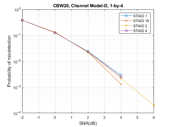
markers = 'ox*sd^v><ph+';
numMarkers = numel(markers);
for u=1:numTxSTAs
    semilogy(snrRange,misdetectionProbability(u,:),['-' markers(mod(u-1,numMarkers)+1)]); hold on;
end
xlabel('SNR(dB)');
ylabel('Probability of misdetection');
dataStr = arrayfun(@(x)sprintf('STAID %d',x),STAID(txSTAIndex),'UniformOutput',false);
title(sprintf('%s, Channel %s, %d-by-%d',chanBW,delayProfile,numTx,numRx));
legend(dataStr);
grid on;
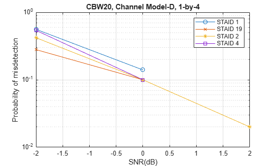
The number of packets tested at each SNR point depends on numPackets. For meaningful results, increase the value of numPackets. This figure was created by running a longer simulation with numPackets:1e4 and snrRange:-2:2:6.
Selected Bibliography
IEEE Std 802.11ax™-2021. IEEE Standard for Information Technology - Telecommunications and Information Exchange between Systems - Local and Metropolitan Area Networks - Specific Requirements - Part 11: Wireless LAN Medium Access Control (MAC) and Physical Layer (PHY) Specifications - Amendment 1: Enhancements for High-Efficiency WLAN.
Montreuil, L. et al. NDP Short Feedback Design. IEEE 802.11-17/0044r4, May 2017.