Estimate Channel Using Input Data and Reference Subcarriers
This example shows how to use the OFDM Channel Estimator block to estimate a channel using input data and reference subcarriers. In this example model, the averaging and interpolation features are enabled. The HDL Algorithm subsystem in this example model supports HDL code generation.
Set Input Data Parameters
Set up these workspace variables for the model to use. You can modify these values according to your requirement.
rng('default');
numOFDMSym = 980;
numOFDMSymToBeAvg = 14;
interpolFac = 3;
maxNumScPerSym = 72;
numOFDMSymPerFrame = 140;
numScPerSym = 72;
Generate Sinusoidal Input Data Subcarriers
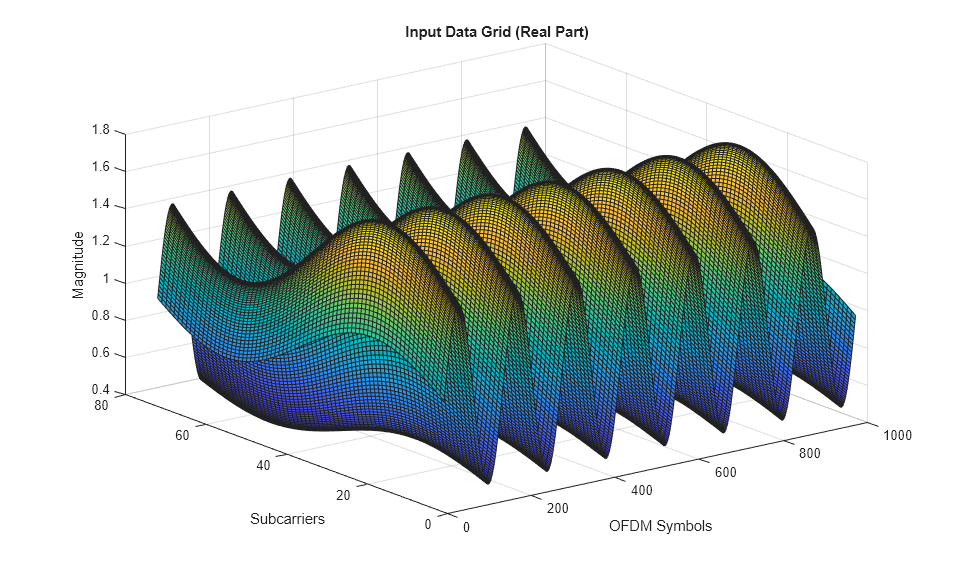
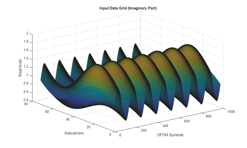
Use the numScPerSym and numOFDMSym variables to generate complex sinusoidal input data subcarriers with their real and imaginary parts generated separately.
dataInGrid = zeros(numScPerSym,numOFDMSym);
for numScPerSymCount = 0:numScPerSym - 1
    for numOFDMSymCount = 0:numOFDMSym - 1
        realXgain = 1 + .2*sin(2*pi*numScPerSymCount/numScPerSym);
        realYgain = 1 + .5*sin(2*pi*numOFDMSymCount/numOFDMSymPerFrame);
        imagXgain = 1 + .3*sin(2*pi*numScPerSymCount/numScPerSym);
        imagYgain = 1 + .4*sin(2*pi*numOFDMSymCount/numOFDMSymPerFrame);
        dataInGrid(numScPerSymCount+1,numOFDMSymCount+1) = realXgain*realYgain + 1i*(imagXgain*imagYgain);
    end
end
validIn = true(1,length(dataInGrid(:)));

figure(1);
surf(real(dataInGrid))
xlabel('OFDM Symbols')
ylabel('Subcarriers')
zlabel('Magnitude')
title('Input Data Grid (Real Part)')

figure(2);
surf(imag(dataInGrid))
xlabel('OFDM Symbols')
ylabel('Subcarriers')
zlabel('Magnitude')
title('Input Data Grid (Imaginary Part)')
Generate Reference Data Subcarriers
Generate reference data subcarriers.
refDataIn = randsrc(size(dataInGrid(:),1),size(dataInGrid(:),2),[1 1]);
refValidIn = boolean(zeros(1,numOFDMSym*numScPerSym));
startRefValidIndex = randi(interpolFac,1,1);
for numOFDMSymCount = 1:numOFDMSym
    refValidIn(startRefValidIndex+(numOFDMSymCount-1)*numScPerSym:interpolFac:numScPerSym*numOFDMSymCount) = true;
end
Generate Signal with Number of Subcarriers per Symbol
Generate a signal with the number of subcarriers per symbol.
numScPerSymIn = numScPerSym*true(1,length(dataInGrid(:)));
resetSig = false(1,length(dataInGrid(:)));
Run Simulink® Model
Run the model. Running the model imports the input signal variables from the MATLAB workspace to the OFDM Channel Estimator block in the model.
modelname = 'genhdlOFDMChannelEstimatorModel';
open_system(modelname);
out = sim(modelname);

Export Stream of Channel Estimates from Simulink to MATLAB® Workspace
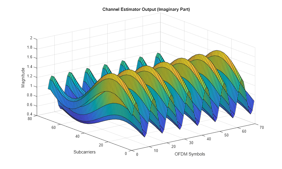
Export the output of the OFDM Channel Estimator block to the MATLAB workspace. Plot the real part and imaginary part of the exported block output.
simOut = out.dataOut.Data(out.validOut.Data);
N = length(simOut) - mod(length(simOut),numScPerSym);
temp = simOut(1:N);
channelEstimateSimOut = reshape(temp,numScPerSym,length(temp)/numScPerSym);

figure(3);
surf(real(channelEstimateSimOut))
xlabel('OFDM Symbols')
ylabel('Subcarriers')
zlabel('Magnitude')
title('Channel Estimator Output (Real Part)')

figure(4);
surf(imag(channelEstimateSimOut))
xlabel('OFDM Symbols')
ylabel('Subcarriers')
zlabel('Magnitude')
title('Channel Estimator Output (Imaginary Part)')

Estimate Channel Using MATLAB Function
Estimate the channel by using the channelEstReference function with the sinusoidal input data subcarriers.
dataOut1 = channelEstReference(...
    numOFDMSymToBeAvg,interpolFac,numScPerSym,numOFDMSym, ...
    dataInGrid(:),validIn,refDataIn,refValidIn,numScPerSymIn);
matlabOut = dataOut1(:);
matOut = zeros(numel(matlabOut)*numScPerSym,1);
for ii= 1:numel(matlabOut)
loadArray = [matlabOut(ii).dataOut; zeros((numel(matlabOut)-1)*numScPerSym,1)];
shiftArray = circshift(loadArray,(ii-1)*numScPerSym);
matOut =  matOut + shiftArray;
end
Compare Simulink Block Output with MATLAB Function Output
Compare the OFDM Channel Estimator block output with channelEstReference function output. Plot the output comparison as a real part and an imaginary part using separate plots.
figure('units','normalized','outerposition',[0 0 1 1])
subplot(2,1,1)
plot(real(matOut(:)));
hold on;
plot(real(simOut(:)));
grid on
legend('MATLAB reference output','Simulink block output')
xlabel('Sample Index')
ylabel('Magnitude')
title('Comparison of Simulink Block and MATLAB Function (Real Part)')

subplot(2,1,2)
plot(imag(matOut(:)));
hold on;
plot(imag(simOut(:)));
grid on
legend('MATLAB reference output','Simulink block output')
xlabel('Sample Index')
ylabel('Magnitude')
title('Comparison of Simulink Block and MATLAB Function (Imaginary Part)')

sqnrRealdB = 10*log10(double(var(real(simOut(:)))/abs(var(real(simOut(:)))-var(real(matOut(:))))));
sqnrImagdB = 10*log10(double(var(imag(simOut(:)))/abs(var(imag(simOut(:)))-var(imag(matOut(:))))));

fprintf('\n OFDM Channel Estimator \n SQNR of real part: %.2f dB',sqnrRealdB);
fprintf('\n SQNR of imaginary part: %.2f dB\n',sqnrImagdB);
 OFDM Channel Estimator
 SQNR of real part: 38.54 dB
 SQNR of imaginary part: 37.77 dB
