Get Started with J1939 Communication in Simulink
This example shows you how to send and receive J1939 Parameter Group (PG) messages in Simulink®.
Vehicle Network Toolbox™ provides J1939 blocks for transmitting and receiving Parameter Groups in Simulink models over Controller Area Networks (CAN). This example performs data transfer over a CAN bus using the J1939 Network Configuration, J1939 Node Configuration, J1939 CAN Transport Layer, J1939 Transmit, and J1939 Receive blocks. The communication takes place on MathWorks® virtual CAN channels connected in a loopback configuration.
Set Up J1939 Block Parameters
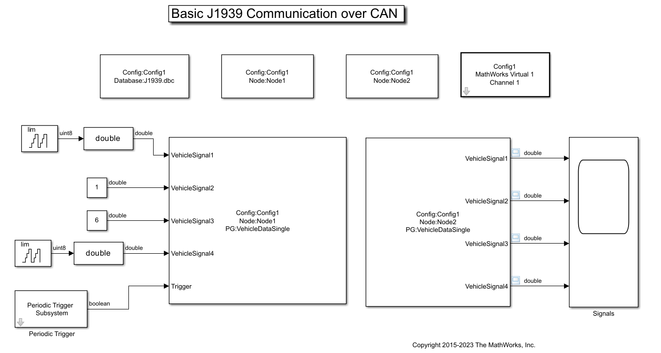
Create a model to set up J1939 communication over the network. The model is configured to transmit and receive a single-frame message between two nodes defined in the J1939 DBC file.
Use a J1939 Network Configuration block and select file
J1939.dbc. This J1939 database file defines two network nodesNode1andNode2, a single-frame messageVehicleDataSingle, and a multi-frame messageVehicleDataMulti.Use a J1939 CAN Transport Layer block and set the Device to MathWorks Virtual 1 (Channel 1). The transport layer is configured to transfer J1939 messages over CAN via the specified channel.
Connect Simulink source blocks such as Counter Limited and Constant to the inputs of a J1939 Transmit block. The J1939 Transmit block is set to queue data for transmission at each timestep when the Trigger port is enabled. For this example, a periodic trigger subsystem sends a high pulse every 50 milliseconds.
Use the J1939 Receive block to receive the messages transmitted over the network.
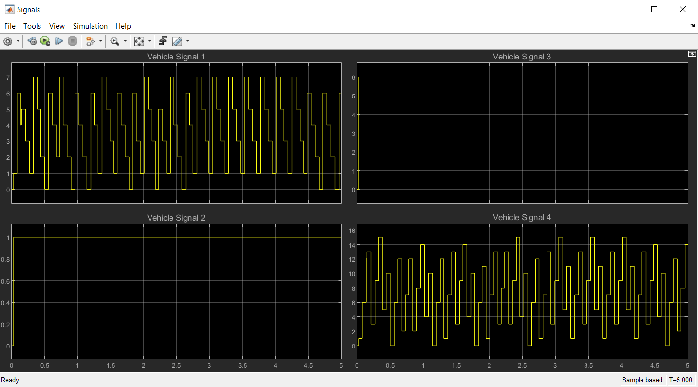
Visualize Signals Received on the Network
Run the Simulink model and observe the received vehicle signal values on the Scope.
For this example, the model is configured to run with Simulation Pacing enabled and Simulation time per wall clock second set to 1. This allows the simulation to slow down and demonstrate near real-time behavior. If you choose to disable Simulation Pacing, Simulink will attempt to simulate as fast as possible while communication over the network happens in wall clock time.
See Also
Tools
- Simulation Pacing Options (Simulink)