Get Started with CAN FD Communication in Simulink
This example shows how to use MathWorks® virtual CAN FD channels to set up transmission and reception of CAN FD messages in Simulink®. The virtual channels are connected in a loopback configuration.
Vehicle Network Toolbox™ provides Simulink blocks for transmitting and receiving live messages via Simulink models over networks utilizing the Controller Area Network Flexible Data (CAN FD) format. This example uses the CAN FD Configuration, CAN FD Pack, CAN FD Transmit, CAN FD Receive and CAN FD Unpack blocks to perform data transfer over a CAN FD bus. These blocks operate similarly to the CAN blocks, but are intended for use only on networks or devices that support the CAN FD protocol.
Transmit and Receive CAN FD Messages
Create a model to transmit and receive a CAN FD message carrying a sine wave data signal. The model transmits a single message per timestep. A DBC file defines the message and signal used in the model.
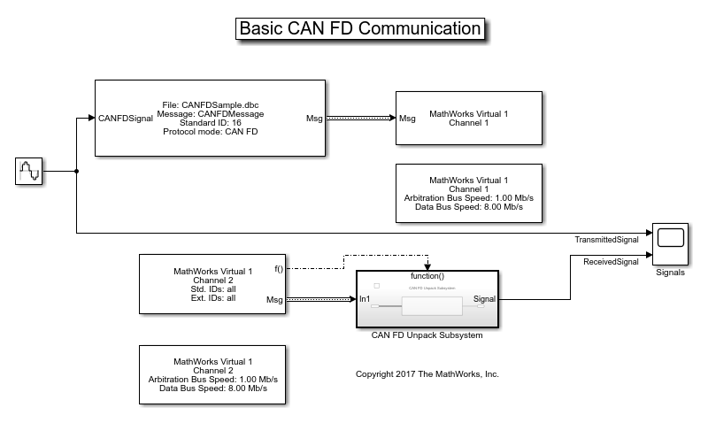
Process CAN FD Messages
The CAN FD Receive block generates a function-call trigger if it receives a new message at any particular timestep. This indicates to other blocks in the model that a message is available for decoding activities. Signal decoding and processing is performed inside the Function-Call Subsystem (Simulink).

Visualize Signal Data
Plot the sine wave values before and after transmission. The X-axis corresponds to the simulation timestep and the Y-axis corresponds to the value of the signal. Note that the phase shift between the two plots represents the propagation delay as the signal travels across the network.

Extend the Example
This example uses MathWorks virtual CAN FD channels. You can connect your models to other supported hardware. You can also modify the model to transmit at periodic rates.