To pixelcontrol
R2026bTo pixelcontrol block
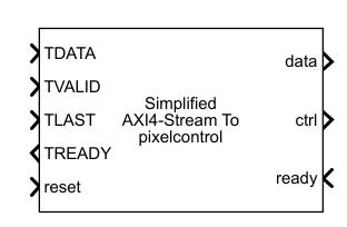
To add a block to a model, double-click the canvas and start typing the block name. Then, select the block from the list.
Libraries:
Vision HDL Toolbox /
I/O Interfaces
Description
The To pixelcontrol block accepts AXI4-Stream
control
signals and converts them to the pixelcontrol bus protocol used by
Vision HDL Toolbox™ blocks. Use this block and the From pixelcontrol
block when your model contains Vision HDL Toolbox blocks and algorithms that use AXI
interfaces.
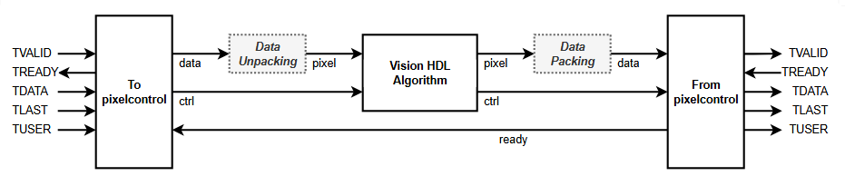
This diagram shows the dataflow using these conversion blocks. The To
pixelcontrol block converts input AXI4-Stream signals to the
pixelcontrol protocol. If you send more than one pixel, or more than one
component per pixel, in each AXI4-Stream transfer, you must unpack the
data output and create a
numPixels-by-numComponents matrix for the
pixel input to the Vision HDL Toolbox algorithm. At the output of the Vision HDL Toolbox algorithm, you can pass a scalar pixel value to the From
pixelcontrol block, or repack
numPixels-by-numComponents values into the
data input.
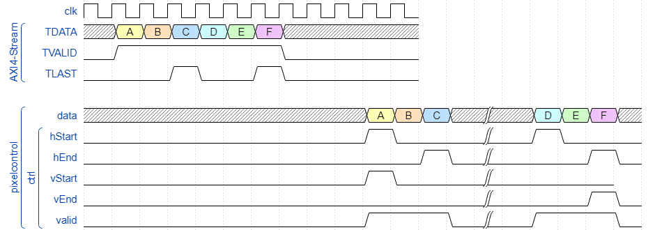
The waveform shows a 2-line-by-3-pixel frame arriving at the input in AXI4-Stream protocol
and the output in pixelcontrol bus protocol. Each AXI4-Stream transfer
represents a single pixel. Each AXI4-Stream packet represents one video line. The
TLAST signal indicates the end of each video line. The block buffers
one line before returning any output, so that the output line has continuous
valid pixels. There is no end-of-frame signal, so the block counts lines
to determine the end of frame. The block adds the specified inactive pixel regions to the
output stream between lines and frames and generates the pixelcontrol
start-of-line (hStart), end-of-line (hEnd),
start-of-frame (vStart), and end-of-frame (vEnd) signals
according to the specified Video format. For more information on the
pixelcontrol protocol, see Streaming Pixel Interface.
Ports
Input
Output
Parameters
To edit block parameters interactively, use the Property Inspector. From the Simulink® Toolstrip, on the Simulation tab, in the Prepare gallery, select Property Inspector.
Select the input control protocol. Both options implement the basics of an AXI4-Stream protocol where each packet represents one video line. The TLAST signal indicates the end of each video line. TDATA contains packed pixel data and TVALID qualifies the data transfer.
Use the
Simplified AXI4-Streamprotocol when you model AXI4-Stream interfaces with MathWorks® library blocks and use the HDL Coder™ IP core workflow. For more information on modeling an AXI4-Stream interface, see Model Design for AXI4-Stream Interface Generation (HDL Coder).Use the
AXI4-Streamprotocol if you model the AXI4-Stream interface yourself, or use external IP blocks.
Specify the number of pixels represented in each TDATA value. The block uses this number to count pixels in lines. For details about Vision HDL Toolbox multipixel support, see Multipixel and Multicomponent Support.
Dimensions of active and inactive regions in a video frame. To select a predefined
format, select from the Video format list. The actual frame
dimensions are displayed in the Video Format Parameters section.
For a custom format, select Custom, and then specify the dimensions
as integers.
The dimensions are defined in the diagram.

Note
The sample time of your video source must match the total number of pixels in the frame of your Frame To Pixels block. The total number of pixels is Total pixels per line × Total video lines, so set the sample time to this value.
If your frame size is large, you may reach the fixed-step solver step size limit for sample times in Simulink, and receive an error like this.
The computed fixed step size (1.0) is 1000000.0 times smaller than all
the discrete sample times in the model.
Video Format | Supported for NumPixels | Active Pixels Per Line | Active Video Lines | Total Pixels Per Line | Total Video Lines | Starting Active Line | Ending Active Line | Front Porch | Back Porch |
|---|---|---|---|---|---|---|---|---|---|
240p | 2 | 320 | 240 | 402 | 324 | 1 | 240 | 44 | 38 |
480p | 2, 4, or 8 | 640 | 480 | 800 | 525 | 36 | 515 | 16 | 144 |
480pH | 2 | 720 | 480 | 858 | 525 | 33 | 512 | 16 | 122 |
576p | 2 or 4 | 720 | 576 | 864 | 625 | 47 | 622 | 12 | 132 |
720p | 2 | 1280 | 720 | 1650 | 750 | 25 | 744 | 110 | 260 |
768p | 2, 4, or 8 | 1024 | 768 | 1344 | 806 | 10 | 777 | 24 | 296 |
1024p | 2, 4, or 8 | 1280 | 1024 | 1688 | 1066 | 42 | 1065 | 48 | 360 |
1080p (default) | 2, 4, or 8 | 1920 | 1080 | 2200 | 1125 | 42 | 1121 | 88 | 192 |
1200p | 2, 4, or 8 | 1600 | 1200 | 2160 | 1250 | 50 | 1249 | 64 | 496 |
2KCinema | - | 2048 | 1080 | 2750 | 1125 | 42 | 1121 | 639 | 63 |
4KUHDTV | 2, 4, or 8 | 3840 | 2160 | 4400 | 2250 | 42 | 2201 | 88 | 472 |
8KUHDTV | 2, 4, or 8 | 7680 | 4320 | 8800 | 4500 | 42 | 4361 | 88 | 1032 |
Custom | If all horizontal dimensions are divisible by
NumPixels. | User- defined | User- defined | User- defined | User- defined | User- defined | User- defined | User- defined | User- defined |
To support these additional formats, select Custom and set
the parameters as shown in this table.
| Video Format | Active Pixels Per Line | Active Video Lines | Total Pixels Per Line | Total Video Lines | Starting Active Line | Ending Active Line | Front Porch | Back Porch |
|---|---|---|---|---|---|---|---|---|
| 480p SDTV | 720 | 480 | 858 | 525 | 37 | 516 | 16 | 122 |
| 576p HDTV | 720 | 576 | 864 | 625 | 45 | 620 | 12 | 132 |
| 720p HDTV | 1280 | 720 | 1650 | 750 | 26 | 745 | 110 | 260 |
| 768p HDTV | 1024 | 768 | 1344 | 806 | 36 | 803 | 24 | 296 |
When using a custom format, the values you enter for the active and inactive dimensions of the image must add up to the total frame dimensions. If you specify a format that does not conform to these rules, the block reports an error.
For the horizontal direction, Total pixels per line must be greater than or equal to Front porch + Active pixels per line. The block calculates Back porch = Total pixels per line − Front porch − Active pixels per line.
For the vertical direction, Total video lines must be greater than or equal to Starting active line + Active video lines − 1. The block calculates Ending active line = Starting active line + Active video lines − 1.
When using the Line Buffer block, or blocks that use an internal line buffer, with a custom video format, further requirements apply:
The horizontal blanking interval, or Back porch + Front porch, must meet these guidelines:
The total of Back porch + Front porch must be at least 2 times the largest kernel size of the algorithm in the blocks following the Frame To Pixel block.
If the kernel size is less than 4, and you are using edge padding, the total porch must be at least 8 pixels.
If you disable padding, the total porch must be at least 12 pixels.
The Back porch must be at least 6 pixels. This parameter is the number of inactive pixels before the first valid pixel in a frame.
For more information on blanking intervals, see Configure Blanking Intervals.
When using multipixel streaming (Number of pixels > 1), these requirements apply.
The video format must have horizontal dimensions divisible by the Number of pixels parameter value. The horizontal dimensions are set by these parameters: Active pixels per line, Total pixels per line, Front porch, and Back porch. Standard video protocols 480p, 768p, 1024p, 1080p, 1200p, 4k UHD, and 8k UHD support Number of pixels equal to 4 or 8.
The minimum input frame size for multipixel streaming is 18 rows by 32 columns.
Choose your kernel size and Active pixels per line such that (Active pixels per line)/(Number of pixels) is at least the kernel width.
Number of video lines to store, specified as a positive integer. The block
implements a FIFO sized for the number of active pixels in a horizontal line specified
by the Video format parameter. For example when you set
Video format to 240p (240 lines with
320 pixels per line), and Maximum lines to buffer is
3, the FIFO can store 2^nextpow2(320*3)=1024
pixels. When the buffer reaches this threshold, the block sets
TREADY to false.
Extended Capabilities
Version History
Introduced in R2026b

