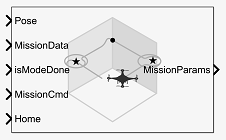
Path Manager
Compute and execute a UAV autonomous mission
Libraries:
UAV Toolbox /
Algorithms
Description
The Path Manager block computes mission parameters for an unmanned aerial vehicle (UAV) by sequentially switching between mission points specified in the MissionData input port. The MissionCmd input port changes the execution order at runtime. The block supports both multirotor and fixed-wing UAV types.
Ports
Input
Current UAV pose, specified as a four-element column vector of
[x;y;z;courseAngle].
x, y, and z is the current
position of the UAV in north-east-down (NED) coordinates specified in meters.
courseAngle specifies the course angle in radians in the range
[-pi, pi].
Data Types: single | double
UAV mission data, specified as a UAVPathManagerBus bus. The
UAVPathManagerBus bus has the three bus elements
mode, position, and
params.
You can use the Constant (Simulink) block to specify the mission
data as an n-by-1 array of structures and set the output data type
to Bus:UAVPathManagerBus. n is the number of
mission points. The fields of each structure are:
mode— Mode of the mission point, specified as an 8-bit unsigned integer between 1 and 6.position— Position of the mission point, specified as a three-element column vector of[x;y;z]. x, y, and z is the position in north-east-down (NED) coordinates specified in meters.params— Parameters of the mission point, specified as a four-element column vector.
The values assigned to the fields, in turn, are assigned to their corresponding
bus elements in the UAVPathManagerBus bus.
This table describes the types of mode and the corresponding
values for the position and params fields in a
mission point structure.
mode | position | params | Mode description |
|---|---|---|---|
uint8(1) | [x;y;z] | [p1;p2;p3;p4] | Takeoff — Take off from the ground and travel toward the specified position |
uint8(2) | [x;y;z] |
yaw
— Yaw angle in radians in the range radius — Transition radius in meters | Waypoint — Navigate to waypoint |
uint8(3) |
x, y, and z is the center of the circular orbit in NED coordinates specified in meters |
radius — Radius of the orbit in meters turnDir — Turn direction, specified as one of these:
numTurns — Number of turns | Orbit — Orbit along the circumference of a circle defined by the parameters |
uint8(4) | [x;y;z] | [p1;p2;p3;p4] | Land — Land at the specified position |
uint8(5) |
The
launch position is specified in the | [p1;p2;p3;p4] | RTL — Return to launch position |
uint8(6) | [x;y;z] |
p1, p2, p3, and p4 are user-specified parameters corresponding to a custom mission point | Custom — Custom mission point |
Note
p1, p2, p3, and p4 are user-specified parameters.
Example: [struct('mode',uint8(1),'position',[0;0;100],'params',[0;0;0;0])]
Data Types: bus
Determine if the mission point was executed, specified as 0
(false) or 1 (true).
Data Types: Boolean
Command to change mission at runtime, specified as an 8-bit unsigned integer between 0 and 3.
This table describes the possible mission commands.
| Mission Command | Description |
|---|---|
uint8(0) | Default — Execute the mission from first to the last mission point in the sequence |
uint8(1) | Hold — Hold at the current mission point Loiter around the current position for fixed-wing and hover at the current position for multirotor UAVs |
uint8(2) | Repeat — Repeat the mission after reaching the last mission point |
uint8(3) | RTL — Execute return to launch (RTL) mode After RTL, the mission resumes if
the |
Data Types: uint8
UAV home location, specified as a three-element column vector of
[x;y;z].
x, y, and z is the position
in north-east-down (NED) coordinates specified in meters.
Data Types: single | double
Output
UAV mission parameters, returned as a 2-by-1 array of buses of the type
UAVPathManagerBus. The first element of the bus array is the
current mission point, and the second element of the bus array is the previous mission
point.
This table describes the output mission parameters depending on the mission mode.
| Current Mission Mode | Output Mission Parameters | |||
|---|---|---|---|---|
| Mission Points | mode | position | params | |
Takeoff | First bus element: Current | uint8(1) | [x;y;z] | [p1;p2;p3;p4] |
Second bus element: Previous |
|
|
| |
Waypoint | First bus element: Current | uint8(2) | [x;y;z] |
yaw
— Yaw angle in radians in the range radius — Transition radius in meters |
Second bus element: Previous |
|
|
courseAngle — Angle of the line
segment between the previous and the current position, specified in
radians in the range | |
Orbit | First bus element: Current | uint8(3) |
x, y, and z is the center of the circular orbit in NED coordinates specified in meters |
radius — Radius of the orbit in meters turnDir — Turn direction, specified as one of these:
numTurns — Number of turns |
Second bus element: Previous |
|
|
| |
Land | First bus element: Current | uint8(4) | [x;y;z] | [p1;p2;p3;p4] |
Second bus element: Previous |
|
|
| |
RTL | First bus element: Current | uint8(5) |
The
launch position is specified in the | [p1;p2;p3;p4] |
Second bus element: Previous |
|
|
| |
Custom | First bus element: Current | uint8(6) | [x;y;z] |
p1, p2, p3, and p4 are user-specified parameters corresponding to a custom mission point |
Second bus element: Previous |
|
|
| |
Note
p1, p2, p3, and p4 are user-specified parameters.
At start of simulation, the previous mission point is set to the Armed mode.
| mode | position | params |
|---|---|---|
uint8(0) |
| [-1;-1;-1;-1] |
Set the end mission point to RTL or Land mode, else the end mission point is automatically set to Hold mode.
This table describes the output mission parameters when the input to the MissionCmd input port is set to Hold mode.
| UAV Type | Output Mission Parameters | |||
|---|---|---|---|---|
| Mission Points | mode | position | params | |
Multirotor | First bus element: Current | uint8(7) | [x;y;z] | [-1;-1;-1;-1] |
Second bus element: Previous |
|
|
| |
Fixed-Wing | First bus element: Current | uint8(7) |
x, y, and z is the center of the circular orbit in NED coordinates specified in meters |
radius
— Loiter radius is specified in the turnDir
— Turn direction is specified as |
Second bus element: Previous |
|
|
| |
Data Types: bus
Parameters
Type of UAV, specified as either multirotor or
fixed-wing.
Tunable: No
Loiter radius for the fixed-wing UAV, specified as a positive numeric scalar in meters.
Dependencies: To enable this parameter, set the UAV
type parameter to fixed-wing.
Tunable: No
Data type of the input mission bus, specified as either double or
single.
Tunable: No
Name of the input mission bus, specified as
'UAVPathManagerBus'.
Tunable: No
Extended Capabilities
C/C++ Code Generation
Generate C and C++ code using Simulink® Coder™.
Version History
Introduced in R2020b
MATLAB Command
You clicked a link that corresponds to this MATLAB command:
Run the command by entering it in the MATLAB Command Window. Web browsers do not support MATLAB commands.
Website auswählen
Wählen Sie eine Website aus, um übersetzte Inhalte (sofern verfügbar) sowie lokale Veranstaltungen und Angebote anzuzeigen. Auf der Grundlage Ihres Standorts empfehlen wir Ihnen die folgende Auswahl: .
Sie können auch eine Website aus der folgenden Liste auswählen:
So erhalten Sie die bestmögliche Leistung auf der Website
Wählen Sie für die bestmögliche Website-Leistung die Website für China (auf Chinesisch oder Englisch). Andere landesspezifische Websites von MathWorks sind für Besuche von Ihrem Standort aus nicht optimiert.
Amerika
- América Latina (Español)
- Canada (English)
- United States (English)
Europa
- Belgium (English)
- Denmark (English)
- Deutschland (Deutsch)
- España (Español)
- Finland (English)
- France (Français)
- Ireland (English)
- Italia (Italiano)
- Luxembourg (English)
- Netherlands (English)
- Norway (English)
- Österreich (Deutsch)
- Portugal (English)
- Sweden (English)
- Switzerland
- United Kingdom (English)