Simulate and Deploy Software Architectures
This example shows how to schedule and simulate the execution order of component functions and generate code.
In this example, a simple software architecture is modeled in System Composer™ containing two components. The export-function component is linked to a Simulink® behavior, export_model_software_architecture. The rate-based component is linked to a Simulink behavior, rate_based_software_architecture.
model = systemcomposer.openModel('RateBasedExportFunctionSoftwareArchitectureModel');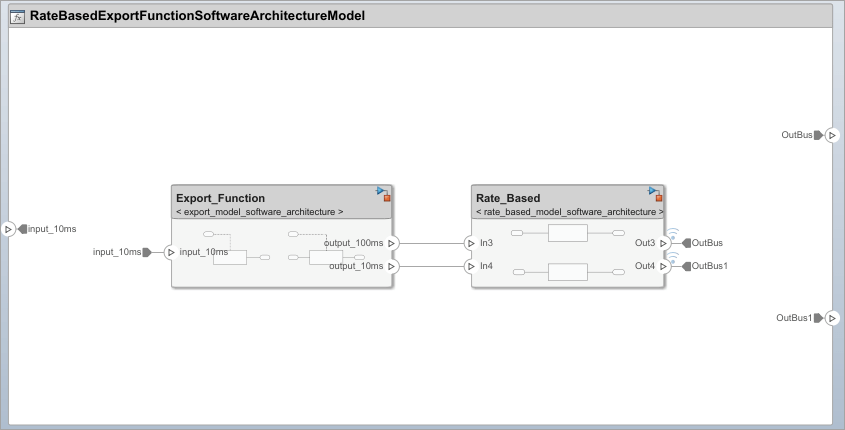
The linked behavior model of the export-function component contains two functions. Each function uses a Function-Call Subsystem block connected to an Inport block that generates periodic function-call events, with sample times of 10ms and 100ms. For details on creating export-function models, see Create Export-Function Model.
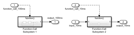
If Inport blocks connected to the function-call input ports use a sample time of -1, the functions are aperiodic. To schedule and simulate aperiodic functions, create a test model that includes explicit scheduling blocks such as a Stateflow® Chart. For more information, see Test Software Architecture.
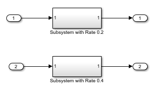
The linked behavior model of the rate-based component contains two subsystems, with sample times of 200ms and 400ms. For details on creating rate-based models, see Create Rate-Based Model.
Simulate Model with Default Execution Order
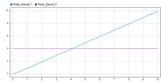
To simulate the model, use the sim function.
sim("RateBasedExportFunctionSoftwareArchitectureModel.slx");To view the output signals of the rate-based component, open the Simulation Data Inspector. Go to the Simulation tab, in the Review Results section, select Data Inspector.
Schedule Component Functions Using Functions Editor
You can use the Functions Editor to change the execution order of component functions and edit the period of functions with an inherited sample time (-1).
To open the Functions Editor, in the toolstrip, on the Modeling tab, in the Design section, click Functions Editor.

On the Functions tab of the Functions Editor, you can view the component functions and schedule the order of execution.
When you open the Functions Editor, the model automatically updates, and the table displays the functions of components in your model.
If the software architecture changes, the Update Model button becomes yellow to signal that an update is required to refresh your functions table.
To change the order of component functions, use the up and down arrows or drag functions to sort them.
To edit sample times of functions, specify their period in the functions table.
You can order functions automatically based on their data dependencies. To enable automatic sorting, select the Order functions by dependency check box. For more information, see Author Functions and Create Function Groups Using Functions Editor.
Alternatively, you can use the increaseExecutionOrder and decreaseExecutionOrder functions of the systemcomposer.arch.Function object to programmatically change function execution order. To order functions by dependency, you can enable the OrderFunctionsByDependency parameter of the architecture model using this command:
set_param('RateBasedExportFunctionSoftwareArchitectureModel','OrderFunctionsByDependency','on');
The OrderFunctionsByDependency parameter is disabled by default.
Test Software Architecture
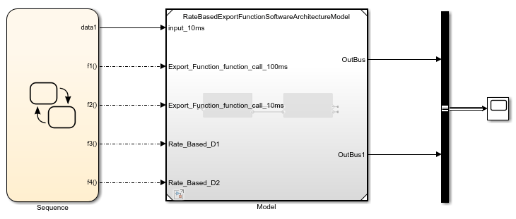
You can test a software architecture model by referencing the architecture in a test model. The Simulink model contains a Stateflow Chart (Stateflow) block to model a more complex scheduling of functions. A Stateflow license is required for this functionality.
In this example, the Model block references the software architecture, RateBasedExportFunctionSoftwareArchitectureModel, and has a function-call input port for each function in the software architecture. To simulate with a Stateflow periodic scheduler, connect the function-call outputs of the chart to the function-call inputs of the Model block.
Generate Code for Software Architecture
You can generate code from the software architecture model for the functions of the export-function and rate-based components. Code generation requires an Embedded Coder® license.
To generate code from the architecture model, on the Apps tab of the toolstrip, select Embedded Coder. Then, on the C Code tab of the toolstrip, select Generate Code.
The generated code contains an entry-point function for each function of the components in the software architecture. For more information on code generation for export-function models, see Generate Code for Export-Function Model.
For the export-function component, the generated code has two functions, one to correspond to each periodic function-call event of the linked behavior model.
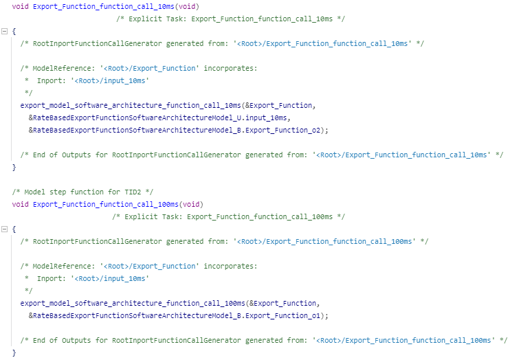
For the rate-based component, the generated code has separate entry-point functions for each sample time in the linked behavior model.

See Also
systemcomposer.createModel | createArchitectureModel | createSimulinkBehavior | increaseExecutionOrder | decreaseExecutionOrder