Electric Drives
Use these examples to learn how to model asynchronous, synchronous, switched reluctance machines and controls.
Featured Examples
Visualize Four-Quadrant Operation of Electric Drive System
Helps you visualize the torque-speed trajectory of a Motor & Drive (System Level) block operated in all four quadrants.
- Since R2025a
- Open Live Script
Design PID Control for DC Motor Using Classical Control Theory
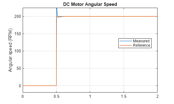
Design a PID controller for a DC Motor using classical control theory. Alternatively, you can use Steady State Manager, Model Linearizer, Frequency Response Estimator, or PID tuner apps to streamline the design.
- Since R2025a
- Open Live Script
Classify Motor Faults Using Deep Learning
Train a deep learning model to classify faults in a permanent magnet synchronous motor (PMSM) using simulated data across various revolutions per minute (RPM). You use Simscape Electrical™ to create the model for a fault scenario, then use Deep Learning Toolbox™ to train a neural network to classify the fault data.
(Deep Learning Toolbox)
- Since R2025a
Control Velocity of Three-Phase PMSM with Open-End Winding
Control the rotor angular velocity in an interior permanent magnet synchronous machine (IPMSM) with an open-end winding. A high-voltage battery feeds the IPMSM through two controlled three-phase converters. The IPMSM operates in both motoring and generating modes according to the load. An ideal torque source provides the load. The Scopes subsystem contains scopes that allow you to see the simulation results. The Control subsystem includes a PI-based field oriented control structure. During the one-second simulation, the angular velocity demand is 0 rpm, 500 rpm, 2000 rpm, and then 3000 rpm.
- Since R2025a
- Open Model
Control and Simulate Torque of IPMSM in DQ Frame
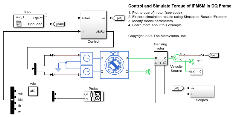
Control the torque in an automotive electrical traction drive of an interior permanent magnet synchronous machine (IPMSM). The example controls and simulates the torque in the rotor direct-quadrature (DQ) reference frame. You can use the DQ reference frame to design the controller and to speed up the simulation. The IPMSM operates in both motoring and generating modes according to the load. An ideal angular velocity source provides the load. The Control subsystem uses an open-loop approach to control the IPMSM torque and a closed-loop approach to control the current. The control algorithm converts the torque request to the relevant current references. The reference DQ voltages feed the IPMSM. The simulation involves several torque steps in both motor and generator modes.
- Since R2024b
- Open Model
Simulate PMSM Drive with Thermal Model in DQ Frame
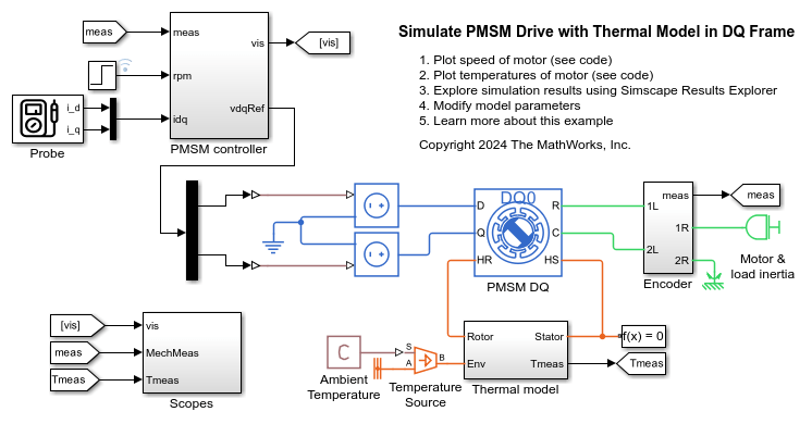
Simulate a permanent magnet synchronous machine (PMSM) in the direct-quadrature (DQ) reference frame. The PMSM contains a thermal model and empirical iron losses. To design the PMSM controller and achieve the desired performance, select the architecture and the gains for the model. The initial temperature of the stator and rotor is 25 degrees Celsius. The ambient temperature is 27 degrees Celsius. The Scopes subsystem contains scopes that allow you to see the simulation results.
- Since R2024b
- Open Model
Control Speed of BLDC Motor Without Position Sensor
Control the speed in a brushless direct current (BLDC) electric drive without a position sensor. A DC voltage source feeds the BLDC through a controlled three-phase inverter. The Control subsystem implements the sensorless speed control strategy. A hysteresis controller controls the phase currents. The Scopes subsystem contains scopes that allow you to see the simulation results.
- Since R2024b
- Open Model
Control Speed of Induction Machine with Six-Step Method
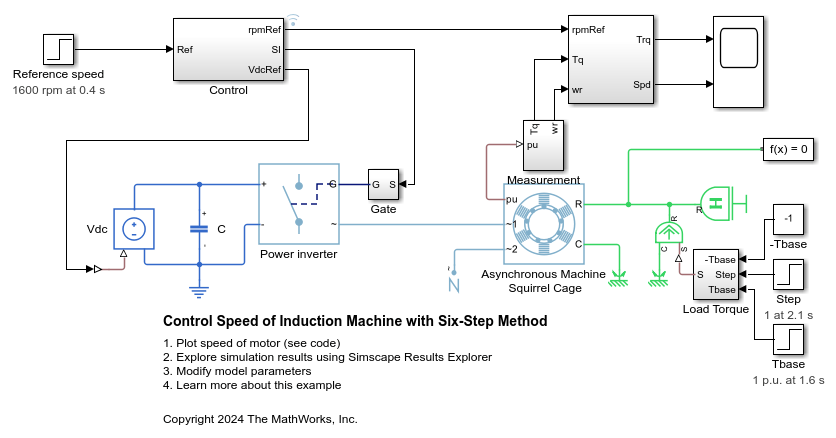
Control the rotor speed in an asynchronous machine (ASM) drive by using the scalar six-step control method. The control algorithm converts the reference speed to a reference frequency. The controller generates the gate pulses from the reference frequency while maintaining a constant voltage-to-frequency ratio.
- Since R2024b
- Open Model
Asynchronous Machine Direct Torque Control
Control an asynchronous machine (ASM) using the direct-torque control method. A PI-based speed controller supplies the torque reference. The direct-torque controller generates the inverter pulses.
Asynchronous Machine Direct Torque Control with Space Vector Modulator
Control an asynchronous machine (ASM) using the direct-torque control method with space vector modulator. A PI-based speed controller supplies the torque reference. The direct-torque controller generates the reference voltages required by the space vector modulator. A DC voltage source feeds the ASM through a controlled average-value voltage source converter.
Asynchronous Machine Scalar Control
Control the rotor speed in an asynchronous machine (ASM) drive using the scalar V/f control method. The converter transforms a reference speed to a reference electrical frequency. The controller generates reference voltages from the reference frequency by maintaining a constant voltage-to-frequency ratio through scalar V/f control.
BLDC Hysteresis Current Control
Control the currents in a BLDC based electrical drive using hysteresis controllers. A DC voltage source feeds the BLDC through a controlled three-phase inverter. A ramp of current request is provided to the motor controller. The load torque is quadratically dependent on the rotor speed. The Control subsystem implements the hysteresis-based current control strategy. The Scopes subsystem contains scopes that allow you to see the simulation results.
BLDC Position Control
Control the rotor angle in a BLDC based electrical drive. An ideal torque source provides the load. The Control subsystem uses a PI-based cascade control structure with three control loops, an outer position control loop, a speed control loop and an inner current control loop. The BLDC is fed by a controlled three-phase inverter. The gate signals for the inverter are obtained from hall signals. The simulation uses step references. The Scopes subsystem contains scopes that allow you to see the simulation results.
BLDC Speed Control
Control the rotor speed in a BLDC based electrical drive. An ideal torque source provides the load. The Control subsystem uses a PI-based cascade control structure with an outer speed control loop and an inner dc-link voltage control loop. The dc-link voltage is adjusted through a DC-DC buck converter. The BLDC is fed by a controlled three-phase inverter. The gate signals for the inverter are obtained from hall signals. The simulation uses speed steps. The Scopes subsystem contains scopes that allow you to see the simulation results.
HESM Torque Control
Control the torque in a hybrid excitation synchronous machine (HESM) based electrical-traction drive. Permanent magnets and an excitation winding excite the HESM. A high-voltage battery feeds the SM through a controlled three-phase converter for the stator windings and through a controlled four quadrant chopper for the rotor winding. An ideal angular velocity source provides the load. The Control subsystem uses an open-loop approach to control the torque and a closed-loop approach to control the current. At each sample instant, the torque request is converted to relevant current references. The current control is PI-based. The simulation uses several torque steps in both the motor and generator modes. The Visualization subsystem contains scopes that allow you to see the simulation results.
HESM Velocity Control
Control the rotor angular velocity in a hybrid excitation synchronous machine (HESM) based electrical-traction drive. Permanent magnets and an excitation winding excite the HESM. A high-voltage battery feeds the HESM through a controlled three-phase converter for the stator windings and through a controlled four quadrant chopper for the rotor winding. An ideal torque source provides the load. The Control subsystem includes a multi-rate PI-based cascade control structure. The control structure has an outer angular-velocity-control loop and three inner current-control loops. The Visualization subsystem contains scopes that allow you to see the simulation results.
IPMSM Torque Control
Control the torque in an interior permanent magnet synchronous machine (IPMSM) based automotive electrical-traction drive. A high-voltage battery feeds the IPMSM through a controlled three-phase converter. The IPMSM operates in both motoring and generating modes according to the load. An ideal angular velocity source provides the load. The Control subsystem uses an open-loop approach to control the IPMSM torque and a closed-loop approach to control the current. At each sample instant, the torque request is converted to relevant current references. The current control is PI-based and uses a sample rate that is faster than the rate that is used for torque control. The simulation uses several torque steps in both motor and generator modes. The task scheduling is designed in Stateflow®. The Scopes subsystem contains scopes that allow you to see the simulation results.
IPMSM Torque-Based Load Control
Control the torque in an interior permanent magnet synchronous motor (IPMSM) based drive. A high-voltage battery feeds the IPMSM through a controlled three-phase inverter. A ramp of torque request is provided to the motor controller. The load torque is quadratically dependent on the rotor speed. The Control subsystem uses an open-loop approach to control the IPMSM torque and a closed-loop approach to control the current. At each sample instant, the torque request is converted to relevant current references. The current control is PI-based and uses a sample rate that is faster than the rate that is used for torque control. The task scheduling is designed in Stateflow®. The Scopes subsystem contains scopes that allow you to see the simulation results.
IPMSM Velocity Control
Control the rotor angular velocity in an interior permanent magnet synchronous machine (IPMSM) based automotive electrical-traction drive. A high-voltage battery feeds the IPMSM through a controlled three-phase converter. The IPMSM operates in both motoring and generating modes according to the load. An ideal torque source provides the load. The Scopes subsystem contains scopes that allow you to see the simulation results. The Control subsystem includes a multi-rate PI-based cascade control structure which has an outer angular-velocity-control loop and two inner current-control loops. The task scheduling in the Control subsystem is implemented as a Stateflow® state machine. During the one-second simulation, the angular velocity demand is 0 rpm, 500 rpm, 2000 rpm, and then 3000 rpm.
PMSM Field-Weakening Control
Control the rotor angular velocity above the nominal velocity in a permanent magnet synchronous machine (PMSM) based electrical-traction drive. A high-voltage battery feeds the PMSM through a controlled three-phase converter. The Control subsystem includes a multi-rate PI-based cascade control structure which has an outer angular-velocity-control loop and two inner current-control loops. The velocity controller generates a torque reference. A zero d-axis controller converts this torque reference to current references. A field weakening controller adjusts the current references to satisfy the voltage constraints above the nominal velocity. A Stateflow® state machine implements the task scheduling in the Control subsystem. During the 0.7 s simulation, the angular velocity demand ramps up from 0 to 4000 rpm. The Scopes subsystem contains scopes that allow you to see the simulation results.
PMSM Position Control
Control the rotor position in a PMSM based electrical drive. An ideal torque source provides the load. The Control subsystem uses a cascade control structure with two control loops, an outer loop for position and speed control, and an inner loop for current control. The states for the estimator design are the electromagnetic torque, the mechanical angular velocity, the mechanical angular position, and the disturbance (load torque). An optimal state-feedback linear quadratic regulator controls the position and speed. A Luenberger observer estimates the load. PI controllers implement the inner current-control loop. A controlled three-phase inverter feeds the PMSM. The simulation uses step references. The Scopes subsystem contains scopes that allow you to see the simulation results.
SM Torque Control
Control the torque in a synchronous machine (SM) based electrical-traction drive. A high-voltage battery feeds the SM through a controlled three-phase converter for the stator windings and a controlled four quadrant chopper for the rotor winding. An ideal angular velocity source provides the load. The Control subsystem uses an open-loop approach to control the torque and a closed-loop approach to control the current. At each sample instant, the torque request is converted to relevant current references. The current control is PI-based. The simulation uses several torque steps in both motor and generator modes. The task scheduling is implemented as a Stateflow® state machine. The Visualization subsystem contains scopes that allow you to see the simulation results.
SM Velocity Control
Control the rotor angular velocity in a synchronous machine (SM) based electrical-traction drive. A high-voltage battery feeds the SM through a controlled three-phase converter for the stator windings and a controlled four quadrant chopper for the rotor winding. An ideal torque source provides the load. The Control subsystem includes a multi-rate PI-based cascade control structure which has an outer angular-velocity-control loop and three inner current-control loops. The task scheduling in the Control subsystem is implemented as a Stateflow® state machine. The Visualization subsystem contains scopes that allow you to see the simulation results.
Switched Reluctance Machine Current Control
Control the current amplitude in a switched reluctance machine (SRM) based electrical drive. A DC voltage source feeds the SRM through a controlled three-arm bridge. An ideal angular velocity source provides the load. The converter turn-on and turn-off angles are maintained constant. A PI-based current controller regulates the current amplitude.
Control Rotor Speed of Switched Reluctance Machine
Control the rotor speed in a switched reluctance machine (SRM) based electrical drive. A DC voltage source feeds the SRM through a controlled three-arm bridge. To achieve both forward and backward rotation, this example adjusts the converter turn-on and turn-off angles using the speed error.
Synchronous Machine State-Space Control
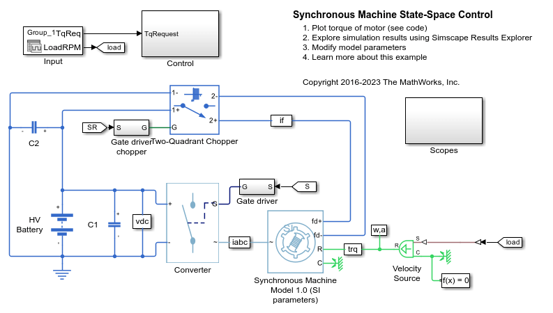
Control currents in a synchronous machine (SM) based traction drive using state-space control. A high-voltage battery feeds the SM through a controlled three-phase converter for the stator windings and through a controlled two-quadrant chopper for the rotor winding. An ideal angular velocity source provides the load. The SM operates below the base speed. At each sample instant, the torque request is converted to relevant current references using the zero d-axis control approach. A state-feedback controller controls the currents in the rotor reference frame. A Luenberger observer obtains the velocity-dependent feedforward pre-control terms. The simulation uses several torque steps in both motor and generator modes. The task scheduling is implemented as a Stateflow® state machine. The Scopes subsystem contains scopes that allow you to see the simulation results.
Synchronous Reluctance Machine Torque Control
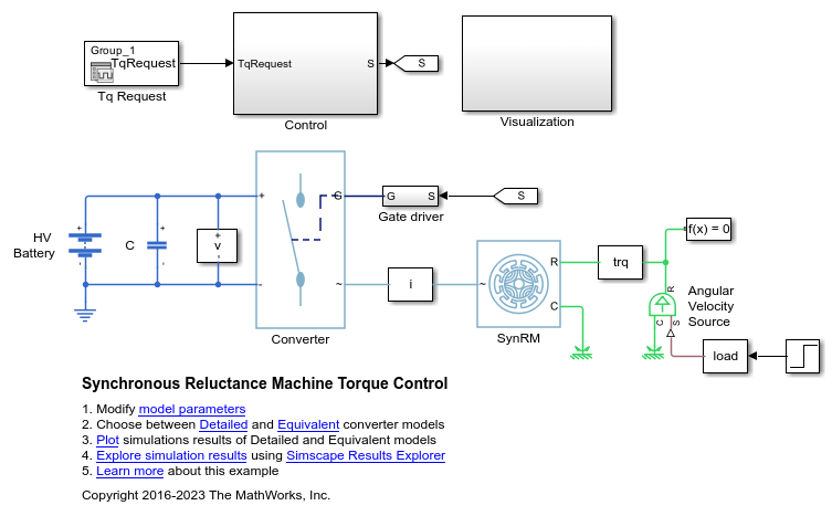
Control the torque in a synchronous reluctance machine (SynRM) based electrical drive. A high-voltage battery feeds the SynRM through a controlled three-phase converter. An ideal angular velocity source provides the load. The Control subsystem uses an open-loop approach to control the torque and a closed-loop approach to control the current. At each sample instant, the torque request is converted to relevant current references using the maximum torque per Ampere strategy. The current control is PI-based. The simulation uses torque steps in both the motor and generator modes. The Visualization subsystem contains scopes that allow you to see the simulation results.
Synchronous Reluctance Machine Velocity Control
Control the rotor angular velocity in a synchronous reluctance machine (SynRM) based electrical drive. A high-voltage battery feeds the SynRM through a controlled three-phase converter. An ideal torque source provides the load. The Control subsystem includes a multi-rate PI-based cascade control structure. The control structure has an outer angular-velocity-control loop and two inner current-control loops. The Visualization subsystem contains scopes that allow you to see the simulation results.
Three-Phase Asynchronous Drive with Sensor Control
Control and analyze the operation of an Asynchronous Machine (ASM) using sensored rotor field-oriented control. The model shows the main electrical circuit, with three additional subsystems containing the controls, measurements, and scopes. The Controls subsystem contains two controllers: one for the Grid-Side Converter (AC/DC) and one for the Machine-Side Converter (DC/AC). The Scopes subsystem contains two time scopes: one for the Grid-Side Converter and one for the ASM. When the model is executed, a Spectrum Analyzer opens and displays frequency data for the A-Phase Supply Current.
Three-Phase Asynchronous Drive with Sensorless Control
Control and analyze the operation of an Asynchronous Machine (ASM) using sensorless rotor field-oriented control. The model shows the main electrical circuit, with three additional subsystems containing the controls, measurements, and scopes. The Controls subsystem contains two controllers: one for the Grid-Side Converter (AC/DC) and one for the Machine-Side Converter (DC/AC). The Scopes subsystem contains two time scopes: one for the Grid-Side Converter and one for the ASM. When the model is executed, a Spectrum Analyzer opens and displays frequency data for the A-Phase Supply Current.
Three-Phase PMSM Drive
A Permanent Magnet Synchronous Machine (PMSM) in wye-wound and delta-wound configuration and an inverter sized for use in a typical hybrid vehicle. The inverter is connected directly to the vehicle battery, but you can also implement a DC-DC converter stage in between. You can use this model to design the PMSM controller, by selecting the architecture and gains to achieve the desired performance. To check the timing of IGBT turn-on and turn-off, you can replace the IGBT devices with the more detailed N-Channel IGBT block. For complete vehicle modeling, you can use the Motor & Drive (System Level) block to abstract the PMSM, inverter, and controller with an energy-based model. The Gmin resistor provides a very small conductance to ground that improves the numerical properties of the model when using a variable-step solver.
Three-Phase PMSM Traction Drive
Control the rotor speed in a permanent magnet synchronous machine (PMSM) based electrical-traction drive. A high-voltage battery feeds the FEM-Parameterized PMSM block through a controlled three-phase converter. A Rotational Friction block provides the load. The position and speed information are obtained by using a high-fidelity resolver. The PMSM controller subsystem includes a cascade control structure which has an outer speed-control loop and two inner current-control loops. During the 0.25 seconds simulation, the rotor speed demand is ramped-up from 0 to 1000 rpm.
Three-Phase Synchronous Machine Control
Control and initialize a Synchronous Machine (SM). The test circuit shows the SM operating as a generator. The terminal voltage is controlled using an AVR and the speed is controlled using a governor.
Three-Phase Synchronous Machine Drive
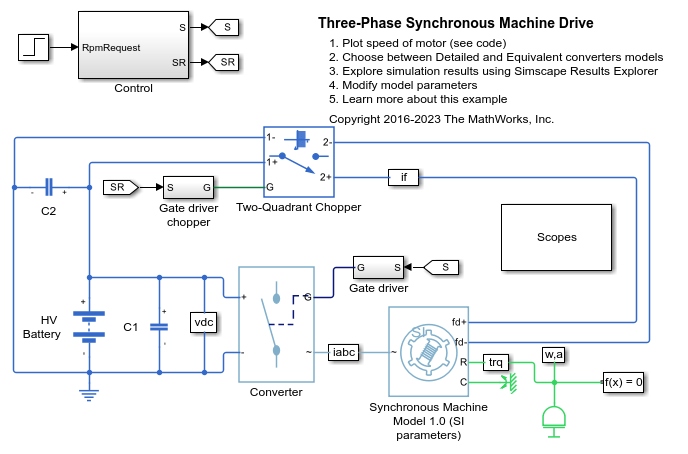
Control the rotor speed in a Synchronous Machine (SM) based electrical drive. A high-voltage battery feeds the SM through a controlled three-phase converter for the stator windings and through a controlled two-quadrant chopper for the rotor winding. Use the model to design the SM controller, selecting architecture and gains to achieve desired performance. The Scopes subsystem contains scopes that allow you to see the simulation results.
Torque Control in Three-Level Converter-Fed Asynchronous Machine Drive
Control the torque in an asynchronous machine (ASM) based electrical-traction drive. A high-voltage battery feeds the ASM through a three-phase three-level neutral-point clamped controlled converter. The ASM operates in both motoring and generating modes. An ideal angular velocity source provides the load. The Control subsystem uses the field-oriented control strategy to control the flux and torque. The current control is PI-based. A proportional controller regulates the neutral point voltage. The simulation uses several torque steps in both motor and generator modes. The Scopes subsystem contains scopes that allow you to see the simulation results.
Single-Phase Asynchronous Machine Direct Torque Control
Control the rotor speed in a single-phase asynchronous machine (ASM) based electrical drive using direct torque control. An ideal torque source provides the load. The Control subsystem uses a cascade control structure. An outer PI-based speed control loop provides the torque and flux references to the direct torque control algorithm from the inner loop. The single-phase ASM is fed by an H bridge. The Scopes subsystem contains scopes that allow you to see the simulation results.
Single-Phase Asynchronous Machine Field-Oriented Control
Control the rotor speed in a single-phase asynchronous machine (ASM) based electrical drive using field-oriented control. An ideal torque source provides the load. The Control subsystem uses a PI-based cascade control structure with an outer speed control loop and two inner current control loops. The single-phase ASM is fed by an H bridge. The Scopes subsystem contains scopes that allow you to see the simulation results.
Five-Phase Switched Reluctance Machine Control
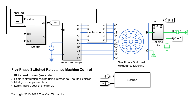
Control the rotor speed in a five-phase switched reluctance machine (SRM) based electrical drive. A DC voltage source feeds the SRM through a controlled five-arm bridge. The converter turn-on and turn-off angles are held constant.
Four-Phase Switched Reluctance Machine Control
Control the rotor speed in a four-phase switched reluctance machine (SRM) based electrical drive. A DC voltage source feeds the SRM through a controlled four-arm bridge. The converter turn-on and turn-off angles are held constant.
Three-Phase Asynchronous Machine Starting
Model a wye-delta starting circuit for an induction machine. When the supply is connected to the machine via switch S1, switch S2 is initially off resulting in the machine being connected in a wye configuration. Once the machine is close to synchronous speed, switch S2 is operated thereby reconnecting the machine in a delta configuration. The higher impedance seen by the supply when the motor is in wye configuration reduces the starting current, and causes less disruption to other connected loads.
HEV PMSM Drive Test Harness
A test harness for a Permanent Magnet Synchronous Motor (PMSM) drive sized for use in a typical hybrid vehicle. The test harness can be used to determine overall drive losses when operating at a given speed and torque. Tabulated losses information from this test harness can then be used by the Simscape™ Electrical™ Motor & Drive (System Level) block for rapid simulation of complete drive cycles whilst still accurately predicting overall system efficiency.
Calculate Performance Curves of BLDC
Calculate performance curves for a brushless DC (BLDC) motor. The simulation includes a speed ramp. Ideal trapezoidal modulation waves are used to drive an average-value converter. A triggered subsystem is used to determine the peak torque, power, current, and efficiency values for a given speed.
Single-Phase PMSM Control
Control the rotor speed in a single-phase permanent magnet synchronous motor (SPPMSM) drive. A DC voltage source feeds the SPPMSM through a controlled H-Bridge. The Control subsystem implements the speed control strategy.
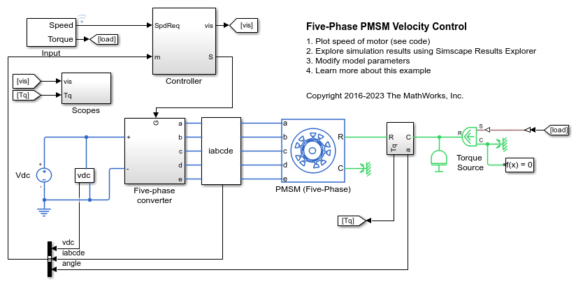
Five-Phase PMSM Velocity Control
Control the rotor angular velocity in an electrical-traction drive based on a five-phase permanent magnet synchronous machine (PMSM). A DC voltage source feeds the PMSM through a controlled five-phase converter. The PMSM operates in both motoring and generating modes according to the load. An ideal torque source provides the load. The Scopes subsystem contains scopes that allow you to see the simulation results. The Control subsystem includes a PI-based cascade control structure that has an outer angular-velocity-control loop and four inner current-control loops. During the one second simulation, the angular velocity demand is 0 rpm, 500 rpm, 2000 rpm, and then 3000 rpm.
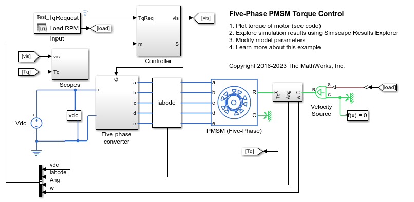
Five-Phase PMSM Torque Control
Control the torque in an electrical-traction drive based on a five-phase permanent magnet synchronous machine (PMSM). A DC voltage source feeds the PMSM through a controlled five-phase converter. The PMSM operates in both motoring and generating modes according to the load. An ideal angular velocity source provides the load. The Control subsystem uses an open-loop approach to control the PMSM torque and a closed-loop approach to control the current. At each sample instant, the torque request is converted to a relevant q-axis current reference. The current control is PI-based. The simulation uses several torque steps in both motor and generator modes. The Scopes subsystem contains scopes that allow you to see the simulation results.
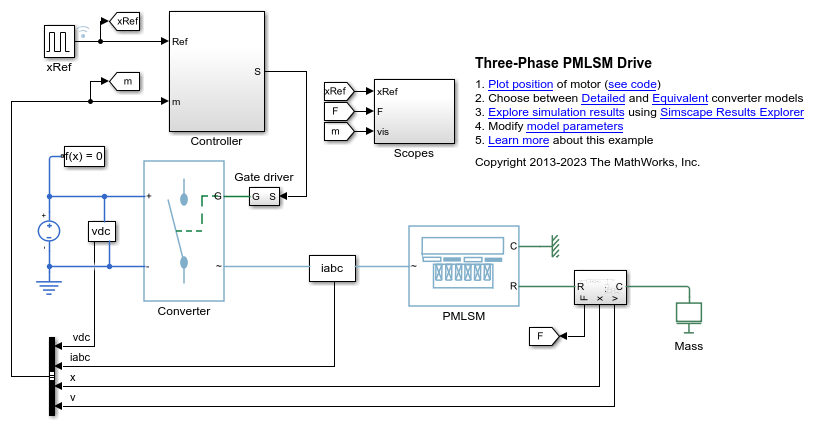
Three-Phase PMLSM Drive
Control the position in a three-phase permanent magnet linear synchronous machine (PMLSM) drive. The Control subsystem uses a PI-based cascade control structure with an outer position control loop, a speed control loop, and two inner current control loops. A controlled three-phase converter feeds the PMLSM. The simulation uses step references. The Scopes subsystem contains scopes that allow you to see the simulation results.
Six-Phase PMSM Torque Control
Control the torque in an electrical-traction drive based on a six-phase permanent magnet synchronous machine (PMSM). A DC voltage source feeds the PMSM through two controlled three-phase converters. The PMSM operates in both motoring and generating modes according to the load. An ideal angular velocity source provides the load. The Control subsystem uses an open-loop approach to control the torque and a closed-loop approach to control the current. At each sample instant, the torque request is converted to a relevant q-axis current reference. The current control is PI-based. The simulation uses several torque steps in both motor and generator modes. The Scopes subsystem contains scopes that allow you to see the simulation results.
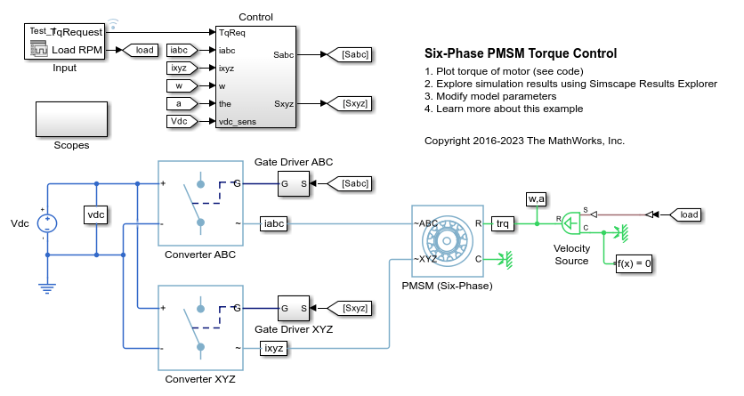
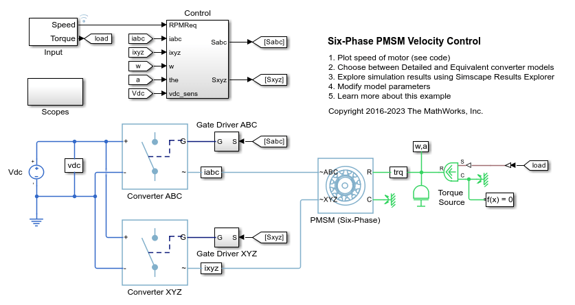
Six-Phase PMSM Velocity Control
Control the rotor angular velocity in an electrical-traction drive based on a six-phase permanent magnet synchronous machine (PMSM). A DC voltage source feeds the PMSM through two controlled three-phase converters. The PMSM operates in both motoring and generating modes according to the load. An ideal torque source provides the load. The Scopes subsystem contains scopes that allow you to see the simulation results. The Control subsystem includes a PI-based cascade control structure that has an outer angular-velocity-control loop and four inner current-control loops. During the one second simulation, the angular velocity demand is 0 rpm, 500 rpm, 2000 rpm, and then 3000 rpm.
BLDC Position Control with Thermal Model
Control the rotor angle in a BLDC based electrical drive. The BLDC includes a thermal model and empirical iron losses. An ideal torque source provides the load. The Control subsystem uses a PI-based cascade control structure with three control loops: an outer position control loop, a speed control loop, and an inner current control loop. The BLDC is fed by a controlled three-phase inverter. The gate signals for the inverter are obtained from hall signals. The simulation uses step references. The initial temperature of the stator windings and rotor is set to 25 degrees Celsius. Ambient temperature is 27 degrees Celsius. The Scopes subsystem contains scopes that allow you to see the simulation results.
Three-Phase PMSM Drive with Thermal Model
A Permanent Magnet Synchronous Machine (PMSM) and an inverter sized for use in a typical hybrid vehicle. The PMSM includes a thermal model and empirical iron losses. The inverter is connected directly to the vehicle battery, but you can also implement a DC-DC converter stage in between. You can use this model to design the PMSM controller, by selecting the architecture and the gains to achieve the desired performance. The initial temperature of the stator windings and rotor is set to 25 degrees Celsius. Ambient temperature is 27 degrees Celsius. The Scopes subsystem contains scopes that allow you to see the simulation results.
Scalar Control in Matrix Converter-Fed Induction Machine Drive
Control the rotor speed in a matrix converter-fed induction machine drive by using the scalar V/f control method. To generate three-phase voltage with reference frequency, the controller maintains a constant voltage-to frequency ratio though scalar V/f control. A three-phase voltage source with fixed amplitude and frequency feeds the induction machine through a three-phase matrix converter. The matric converter is controlled using third harmonic injection Venturini modulation with unity input displacement factor. The induction machine operates in both motoring and generating modes. The Scopes subsystem contains scopes that allow you to see the simulation results.
Faulted PMSM
Model a faulted permanent magnet synchronous motor (PMSM) using Simscape™ Electrical™. Normally when modeling a PMSM, you can represent each winding as a single entity with associated inductance, induced back electromotive force (EMF), and mutual inductive coupling to adjacent windings. However, when a winding fault occurs, the single entity assumption breaks down. To correctly capture the resulting dynamics, you have to model the motor at a winding slot level. This requires modeling in the magnetic domain.
Four-Phase PMSM Torque Control
Control the torque in an electrical-traction drive based on a four-phase permanent magnet synchronous machine (PMSM). A DC voltage source feeds the PMSM through a controlled four-phase converter. The PMSM operates in both motoring and generating modes according to the load. An ideal angular velocity source provides the load. The Control subsystem uses an open-loop approach to control the PMSM torque and a closed-loop approach to control the current. At each sample instant, the torque request is converted to a relevant q-axis current reference. The current control is PI-based. The simulation uses several torque steps in both motor and generator modes. The Scopes subsystem contains scopes that allow you to see the simulation results.
Four-Phase PMSM Velocity Control
Control the rotor angular velocity in an electrical-traction drive based on a four-phase permanent magnet synchronous machine (PMSM). A DC voltage source feeds the PMSM through a controlled four-phase converter. The PMSM operates in both motoring and generating modes according to the load. An ideal torque source provides the load. The Scopes subsystem contains scopes that allow you to see the simulation results. The Control subsystem includes a PI-based cascade control structure that has an outer angular-velocity-control loop and four inner current-control loops. During the one second simulation, the angular velocity demand is 0 rpm, 500 rpm, 2000 rpm, and then 3000 rpm.
Six-Phase Switched Reluctance Machine Control
Control the rotor speed in an electrical drive based on a six-phase switched reluctance machine (SRM). A DC voltage source feeds the SRM through a controlled six-arm bridge. The converter turn-on and turn-off angles are constant.
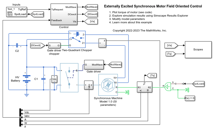
Externally Excited Synchronous Motor Field Oriented Control
Control the torque in an externally excited synchronous motor (SM) drive by using field-oriented control. A high-voltage battery feeds the SM through a controlled three-phase converter for the stator windings and through a controlled two-quadrant chopper for the rotor winding. Both converters are controlled using Averaged Switch and modulation waveforms for fast simulation. The implementation allows you to easily switch to PWM control signals. Current references for the d-axis, q-axis, and excitation are generated offline and implemented using 3-D lookup tables. Use the model to design and evaluate in real-time the SM control algorithm. For controller deployment on an embedded microcontroller, use optimized controllers from the Motor Control Blockset™ libraries. The Scopes subsystem contains scopes that allow you to see the simulation results.
System-Level AC Drive
Model a system-level AC drive for an electric machine by using the AC-DC Converter (Three-Phase) block and Motor & Drive (System Level) block. The AC-DC converter represents a grid-side converter which provides a constant DC-link voltage. The Motor & Drive block acts as a generic AC electric machine with its DC-AC converter. This modeling approach provides fast system-level simulation without the switching events of the power converters.
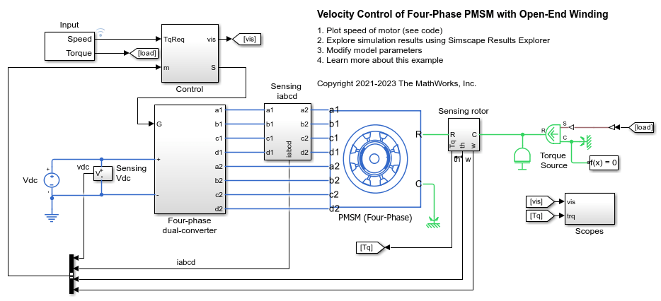
Velocity Control of Four-Phase PMSM with Open-End Winding
Control the rotor angular velocity in an electrical-traction drive that uses a four-phase permanent magnet synchronous machine (PMSM) with an open-end winding. To view the source code of the Open-End PMSM (Four-Phase) block, double-click the block and then click the 'Source code' hyperlink in the Description tab. A DC voltage source feeds the PMSM through two controlled four-phase converters. The PMSM operates in both motoring and generating modes according to the load. An ideal torque source provides the load. The Scopes subsystem contains scopes that allow you to see the simulation results. The Control subsystem includes a PI-based cascade control structure that has an outer angular-velocity-control loop and four inner current-control loops. During the one second simulation, the angular velocity demand is 0 rpm, 500 rpm, 2000 rpm, and then 3000 rpm.
Model Start-Up Control Strategy for Wound-Rotor Induction Motor
Design a start-up control strategy with a resistor for a wound-rotor induction model using a Simscape™ Electrical™ FEM-Parameterized Induction Machine (Wound Rotor) block.
- Since R2023b
- Open Live Script
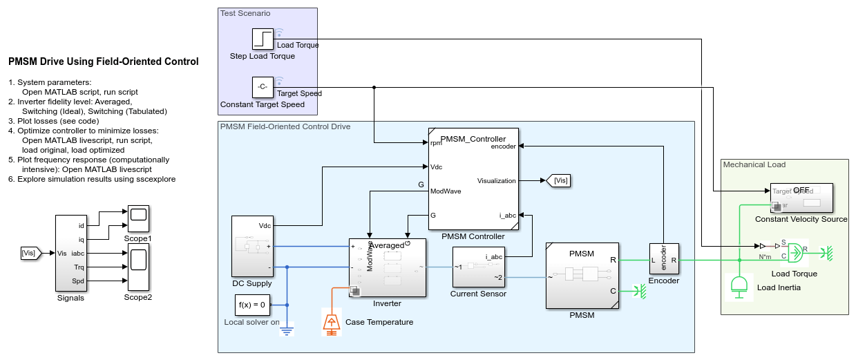
Improve Motor Efficiency with Optimized Control Parameters
Improve the efficiency of a permanent magnet synchronous motor (PMSM) drive using an optimal field-oriented controller (FOC). The FOC has been designed to minimize the motor losses. You can download this model in MATLAB® or access it from MATLAB Central File Exchange and GitHub®.
- Since R2023b
- Open Live Script
MATLAB Command
You clicked a link that corresponds to this MATLAB command:
Run the command by entering it in the MATLAB Command Window. Web browsers do not support MATLAB commands.
Website auswählen
Wählen Sie eine Website aus, um übersetzte Inhalte (sofern verfügbar) sowie lokale Veranstaltungen und Angebote anzuzeigen. Auf der Grundlage Ihres Standorts empfehlen wir Ihnen die folgende Auswahl: .
Sie können auch eine Website aus der folgenden Liste auswählen:
So erhalten Sie die bestmögliche Leistung auf der Website
Wählen Sie für die bestmögliche Website-Leistung die Website für China (auf Chinesisch oder Englisch). Andere landesspezifische Websites von MathWorks sind für Besuche von Ihrem Standort aus nicht optimiert.
Amerika
- América Latina (Español)
- Canada (English)
- United States (English)
Europa
- Belgium (English)
- Denmark (English)
- Deutschland (Deutsch)
- España (Español)
- Finland (English)
- France (Français)
- Ireland (English)
- Italia (Italiano)
- Luxembourg (English)
- Netherlands (English)
- Norway (English)
- Österreich (Deutsch)
- Portugal (English)
- Sweden (English)
- Switzerland
- United Kingdom (English)

