PWM Generator (Three-phase, Two-level)
Generate three-phase, two-level pulse width modulated waveform

Libraries:
Simscape /
Electrical /
Control /
Pulse Width Modulation
Description
The PWM Generator (Three-phase, Two-level) block controls switching behavior for a three-phase, two-level power converter. The block:
Calculates on- and off-gating times based on the block inputs:
Three sinusoidal reference voltages, one per phase
A DC-link voltage
Uses the gating times to generate six switch-controlling pulses.
Uses the gating times to generate modulation waveforms.
Continuous and Discontinuous PWM
The block provides modes for both continuous and discontinuous pulse width modulation (PWM). The figure shows the general difference between continuous sinusoidal PWM (SPWM) and continuous space vector modulation (SVM) waveforms.

For discontinuous PWM (DPWM), the block clamps the modulation wave to the positive or negative DC rail for a total of 120 degrees during each fundamental period. During the clamping intervals, modulation discontinues.
A waveform with 30-degree DPWM has four 30-degree intervals per fundamental period.

Selecting a positive or negative 30-degree phase shift affects the clamping intervals for 60-degree DPWM.

The figure shows the waveforms for positive and negative DC clamping for 120-degree DPWM.

Sampling Mode
This block allows you to choose natural, symmetric, or asymmetric sampling of the modulation wave.
The PWM Generator (Three-phase, Two-level) block does not perform carrier-based PWM. Instead, the block uses input signals to calculate gating times and then uses the gating times to generate both the switch-controlling pulses and the modulation waveforms that it outputs.
Carrier-based PWM is, however, useful for showing how the sampling mode that you select relates to the switch-on and switch-off behavior of the pulses that the block generates. A generator that uses a two-level, carrier-based PWM method:
Samples a reference wave.
Compares the sample to a triangle carrier wave.
Generates a switch-on pulse if a sample is higher than the carrier signal or a switch-off pulse if a sample is lower than the carrier wave.
To determine switch-on and switch-off pulse behavior, a two-level carrier-based PWM generator uses these methods to sample the triangle wave:
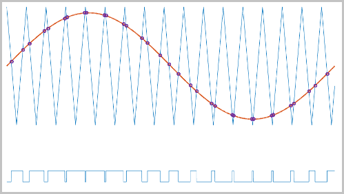
Natural — The sampling and comparison occur at the intersection points of the modulation wave and the carrier wave.
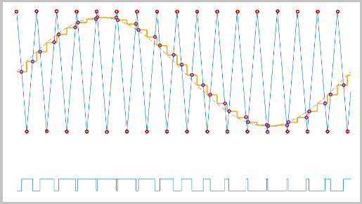
Asymmetric — Sampling occurs at the upper and lower boundaries of the carrier wave. The comparison occurs at the intersection that follows the sampling.
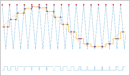
Symmetric — Sampling occurs at only the upper boundary of the carrier wave. The comparison occurs at the intersection that follows the sampling.
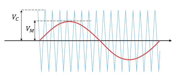
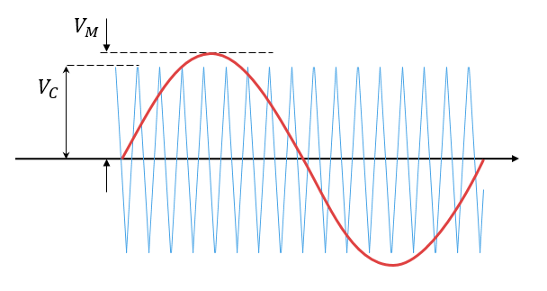
Overmodulation
The modulation index, which measures the ability of the power converter to output a given voltage, is defined as
where
m is the modulation index.
Vm is the peak value of the modulation wave.
Vc is the peak value of the triangle carrier wave.
For three-phase SPWM,
where
Vpeak is the peak value of the fundamental component of the phase-to-neutral voltage.
vdc is the DC-link voltage.
For three-phase space-vector PWM (SVM) and DPWM,
For normal steady-state operation, 0 <m ≤
1. If a transient, such as a load increase, causes the
amplitude of Vm to exceed the amplitude of
Vc, overmodulation
(m > 1) occurs.
If overmodulation occurs, the output voltage of the power converter clamps to the positive or negative DC rail.
In the Three-Phase Two-Level PWM Generator example, the Two-Level Controller subsystem contains a 400–V DC-link input, and a modulation index, m, of 0.8. For SPWM, the maximal input voltage is 400 V/2, that is, 200 V. To demonstrate overmodulation, a transient is added at the beginning of the simulation. The transient forces the amplitudes of the reference voltages to exceed the amplitude of 1/2 of the DC-link voltage. To highlight overmodulation, the scope includes simulation results for only one of the six output pulses and only the a-phase of the reference voltages, modulation waveforms, and output voltages.

The modulation index is greater than one between 0.03–0.09 seconds. During overmodulation:
The pulse remains in the on or off position.
The output voltage, Vao, clamps to the positive or negative DC rail.
Examples

Asynchronous Machine Scalar Control
Control the rotor speed in an asynchronous machine (ASM) drive using the scalar V/f control method. The converter transforms a reference speed to a reference electrical frequency. The controller generates reference voltages from the reference frequency by maintaining a constant voltage-to-frequency ratio through scalar V/f control.

Electric Engine Dyno
Model an electric vehicle dynamometer test. The test environment contains an asynchronous machine (ASM) and an interior permanent magnet synchronous machine (IPMSM) connected back-to-back through a mechanical shaft. Both machines are fed by high-voltage batteries through controlled three-phase converters. The 164 kW ASM produces the load torque. The 35 kW IPMSM is the electric machine under test. The Control Machine Under Test (IPMSM) subsystem controls the torque of the IPMSM. The controller includes a multi-rate PI-based control structure. The rate of the open-loop torque control is slower than the rate of the closed-loop current control. The task scheduling for the controller is implemented as a Stateflow® state machine. The Control Load Machine (ASM) subsystem uses a single rate to control the speed of the ASM. The Visualization subsystem contains scopes that allow you to see the simulation results.

Energy Balance in a 48V Starter Generator
An interior permanent magnet synchronous machine (IPMSM) used as a starter/generator in a simplified 48V automotive system. The system contains a 48V electric network and a 12V electric network. The internal combustion engine (ICE) is represented by basic mechanical blocks. The IPMSM operates as a motor until the ICE reaches the idle speed and then it operates as a generator. The IPMSM supplies power to the 48V network, which contains the R3 power consumer. The 48V network supplies power to the 12V network which has two consumers: R1 and R2. The total simulation time (t) is 0.5 seconds. At t = 0.05 seconds, the ICE turns on. At t = 0.1 seconds, R3 switches on. At t = 0.3 seconds, R2 switches on and increases the load on the 12V electric network. The EM Controller subsystem includes a multi-rate PI-based cascade control structure which has an outer voltage-control loop and two inner current-control loops. The task scheduling in the Control subsystem is implemented as a Stateflow® state machine. The DCDC Controller subsystem implements a simple PI controller for the DC-DC Buck converter, which feeds the 12V network. The Scopes subsystem contains scopes that allow you to see the simulation results.

HESM Torque Control
Control the torque in a hybrid excitation synchronous machine (HESM) based electrical-traction drive. Permanent magnets and an excitation winding excite the HESM. A high-voltage battery feeds the SM through a controlled three-phase converter for the stator windings and through a controlled four quadrant chopper for the rotor winding. An ideal angular velocity source provides the load. The Control subsystem uses an open-loop approach to control the torque and a closed-loop approach to control the current. At each sample instant, the torque request is converted to relevant current references. The current control is PI-based. The simulation uses several torque steps in both the motor and generator modes. The Visualization subsystem contains scopes that allow you to see the simulation results.

HESM Velocity Control
Control the rotor angular velocity in a hybrid excitation synchronous machine (HESM) based electrical-traction drive. Permanent magnets and an excitation winding excite the HESM. A high-voltage battery feeds the HESM through a controlled three-phase converter for the stator windings and through a controlled four quadrant chopper for the rotor winding. An ideal torque source provides the load. The Control subsystem includes a multi-rate PI-based cascade control structure. The control structure has an outer angular-velocity-control loop and three inner current-control loops. The Visualization subsystem contains scopes that allow you to see the simulation results.

IPMSG Voltage Stabilization
Control an Interior Permanent Magnet Synchronous Generator (IPMSG) based low voltage generator system for a hybrid electric vehicle (HEV). The Control subsystem includes a multi-rate PI-based cascade control structure which has an outer voltage-control loop and two inner current-control loops. The task scheduling in the Control subsystem is implemented as a Stateflow® state machine. The Scopes subsystem contains scopes that allow you to see the simulation results. An ideal angular velocity source, which represents a combustion engine, drives the IPMSG. The IPMSG supplies low-voltage power to loads R1 and R2. At t = 0.4 seconds, the switch closes, increasing the load.

IPMSM Torque Control in a Parallel HEV
A simplified parallel hybrid electric vehicle (HEV). An interior permanent magnet synchronous machine (IPMSM) and an internal combustion engine (ICE) provide the vehicle propulsion. The IPMSM operates in both motoring and generating modes. The vehicle transmission and differential are implemented using a fixed-ratio gear-reduction model. The Vehicle Controller subsystem converts the driver inputs into torque commands. The vehicle control strategy is implemented as a Stateflow® state machine. The ICE Controller subsystem controls the torque of the combustion engine. The Drive Controller subsystem controls the torque of the IPMSM. The Scopes subsystem contains scopes that allow you to see the simulation results.

IPMSM Torque Control in a Series HEV
An interior permanent magnet synchronous machine (IPMSM) propelling a simplified series hybrid electric vehicle (HEV). An ideal DCDC converter, connected to a high-voltage battery, feeds the IPMSM through a controlled three-phase converter. A combustion engine driven generator charges the high-voltage battery. The vehicle transmission and differential are implemented using a fixed-ratio gear-reduction model. The Vehicle Controller subsystem converts the driver inputs into relevant commands for the IPMSM and generator. The Drive Controller subsystem controls the torque of the IPMSM. The controller includes a multi-rate PI-based control structure. The rate of the open-loop torque control is slower than the rate of the closed-loop current control. The task scheduling for the controller is implemented as a Stateflow® state machine. The Scopes subsystem contains scopes that allow you to see the simulation results.

IPMSM Torque Control in a Series-Parallel HEV
A simplified series-parallel hybrid electric vehicle (HEV). An interior permanent magnet synchronous machine (IPMSM) and an internal combustion engine (ICE) provide the vehicle propulsion. The ICE also uses electric generator to recharge the high-voltage battery during driving. The vehicle transmission and differential are implemented using a fixed-ratio gear-reduction model. The Vehicle Controller subsystem converts the driver inputs into torque commands. The vehicle control strategy is implemented as a Stateflow® state machine. The ICE Controller subsystem controls the torque of the combustion engine. The Generator Controller subsystem controls the torque of the electric generator. The Drive Controller subsystem controls the torque of the IPMSM. The Scopes subsystem contains scopes that allow you to see the simulation results.

IPMSM Torque Control in an Axle-Drive HEV
An interior permanent magnet synchronous machine (IPMSM) propelling a simplified axle-drive electric vehicle. A high-voltage battery feeds the IPMSM through a controlled three-phase converter. The IPMSM operates in both motoring and generating modes. The vehicle transmission and differential are implemented using a fixed-ratio gear reduction model. The Vehicle Controller subsystem converts the driver inputs into a relevant torque command. The Drive Controller subsystem controls the torque of the IPMSM. The controller includes a multi-rate PI-based control structure. The rate of the open-loop torque control is slower than the rate of the closed-loop current control. The task scheduling for the controller is implemented as a Stateflow® state machine. The Scopes subsystem contains scopes that allow you to see the simulation results.

IPMSM Velocity Control
Control the rotor angular velocity in an interior permanent magnet synchronous machine (IPMSM) based automotive electrical-traction drive. A high-voltage battery feeds the IPMSM through a controlled three-phase converter. The IPMSM operates in both motoring and generating modes according to the load. An ideal torque source provides the load. The Scopes subsystem contains scopes that allow you to see the simulation results. The Control subsystem includes a multi-rate PI-based cascade control structure which has an outer angular-velocity-control loop and two inner current-control loops. The task scheduling in the Control subsystem is implemented as a Stateflow® state machine. During the one-second simulation, the angular velocity demand is 0 rpm, 500 rpm, 2000 rpm, and then 3000 rpm.

SM Torque Control
Control the torque in a synchronous machine (SM) based electrical-traction drive. A high-voltage battery feeds the SM through a controlled three-phase converter for the stator windings and a controlled four quadrant chopper for the rotor winding. An ideal angular velocity source provides the load. The Control subsystem uses an open-loop approach to control the torque and a closed-loop approach to control the current. At each sample instant, the torque request is converted to relevant current references. The current control is PI-based. The simulation uses several torque steps in both motor and generator modes. The task scheduling is implemented as a Stateflow® state machine. The Visualization subsystem contains scopes that allow you to see the simulation results.

SM Velocity Control
Control the rotor angular velocity in a synchronous machine (SM) based electrical-traction drive. A high-voltage battery feeds the SM through a controlled three-phase converter for the stator windings and a controlled four quadrant chopper for the rotor winding. An ideal torque source provides the load. The Control subsystem includes a multi-rate PI-based cascade control structure which has an outer angular-velocity-control loop and three inner current-control loops. The task scheduling in the Control subsystem is implemented as a Stateflow® state machine. The Visualization subsystem contains scopes that allow you to see the simulation results.

Synchronous Reluctance Machine Velocity Control
Control the rotor angular velocity in a synchronous reluctance machine (SynRM) based electrical drive. A high-voltage battery feeds the SynRM through a controlled three-phase converter. An ideal torque source provides the load. The Control subsystem includes a multi-rate PI-based cascade control structure. The control structure has an outer angular-velocity-control loop and two inner current-control loops. The Visualization subsystem contains scopes that allow you to see the simulation results.

Three-Phase Asynchronous Drive with Sensor Control
Control and analyze the operation of an Asynchronous Machine (ASM) using sensored rotor field-oriented control. The model shows the main electrical circuit, with three additional subsystems containing the controls, measurements, and scopes. The Controls subsystem contains two controllers: one for the Grid-Side Converter (AC/DC) and one for the Machine-Side Converter (DC/AC). The Scopes subsystem contains two time scopes: one for the Grid-Side Converter and one for the ASM. When the model is executed, a Spectrum Analyzer opens and displays frequency data for the A-Phase Supply Current.

Three-Phase Asynchronous Drive with Sensorless Control
Control and analyze the operation of an Asynchronous Machine (ASM) using sensorless rotor field-oriented control. The model shows the main electrical circuit, with three additional subsystems containing the controls, measurements, and scopes. The Controls subsystem contains two controllers: one for the Grid-Side Converter (AC/DC) and one for the Machine-Side Converter (DC/AC). The Scopes subsystem contains two time scopes: one for the Grid-Side Converter and one for the ASM. When the model is executed, a Spectrum Analyzer opens and displays frequency data for the A-Phase Supply Current.

Three-Phase Two-Level PWM Generator
Use the PWM Generator (Three-phase, Two-level) to control a Converter. The inputs to the PWM Generator are reference AC waveforms and a DC-link voltage of 400 V. There is one time scope for the controller waveforms.
Ports
Input
Output
Parameters
References
[1] Chung, D. W., J. S. Kim, and S. K. Sul. “Unified Voltage Modulation Technique for Real Time Three-Phase Power Conversion.” IEEE Transactions on Industry Applications, Vol. 34, No. 2, 1998, pp. 374–380.
[2] Hava, A. M., R. J. Kerkman, and T. A. Lipo. “Simple Analytical and Graphical Methods for Carrier-Based PWM-VSI Drives.” IEEE Transactions on Power Electronics, Vol. 14, No. 1, 1999, pp. 49–61.