Main Content

DC Voltage Controller

Discrete-time DC voltage PI control with feedforward zero cancellation and integral anti-windup

  • DC Voltage Controller block

Libraries:
Simscape / Electrical / Control / General Machine Control

Description

The DC Voltage Controller block implements discrete-time PI-based DC voltage control. The block can implement zero cancellation in the feedforward path. To avoid saturation of the integral gain, the block can implement anti-windup gain.

Equations

The equation that the DC Voltage Controller block uses to calculate the control signal is

control=(Kp+KiTszz1)(vrefv),

where:

  • control is the control signal, which is expressed as a duty cycle or a current.

  • Kp is the proportional gain.

  • Ki is the integral gain.

  • Ts is the sample time.

  • vref is the reference voltage.

  • v is the measured voltage.

The PI control calculation yields a zero in the closed-loop transfer function. To cancel the zero, the block uses this discrete-time zero-cancellation transfer function:

GZC(z)=TsKiKpz+(TsKpKiKpKi).

To avoid saturation of the integrator output, the block uses an anti-windup mechanism. The integrator gain is then equal to

Ki+Kaw(controlsatcontrolunsat),

where:

  • Kaw is the anti-windup gain.

  • controlsat is the saturated control signal, which the block calculates as controlsat=min(max(controlunsat,controlmin),controlmax),

    where:

    • controlunsat is the unsaturated control signal.

    • controlmin is the lower limit for the control signal.

    • vmax is the upper limit for the control signal.
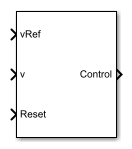
Ports

Input

expand all

Desired DC output voltage for the plant.

Data Types: single | double

Measured DC output voltage for the plant.

Data Types: single | double

External reset signal (rising edge) for the integrator.

Data Types: single | double

Output

expand all

Control signal, control, expressed as a duty cycle or a current.

Data Types: single | double

Parameters

expand all

Proportional gain, Kp, of the controller.

Integral gain, Ki, of the controller.

Anti-windup gain, Kaw, of the controller.

Upper limit for the Control output signal. The value must be greater than the value of the Control action lower limit parameter.

Lower limit for the Control output signal.

Time, in s, between consecutive block executions. During execution, the block produces outputs and, if appropriate, updates its internal state. For more information, see What Is Sample Time? and Specify Sample Time.

If this block is inside a triggered subsystem, inherit the sample time by setting this parameter to -1. If this block is in a continuous variable-step model, specify the sample time explicitly using a positive scalar.

Time, in s, between consecutive discretizations.

Time constant, τ, for the DC voltage filter.

Dependencies

The Time constant voltage filter parameter is only visible when the Filter DC voltage checkbox is selected.

Option to use zero cancellation on the feedforward path.

Dependencies

If you select the Enable zero cancellation option and set Sample time (-1 for inherited) to -1, the Discretization sample time parameter becomes visible.

To enable the filter on voltage measurement path, select the checkbox. To disable the filter, clear the check box.

Dependencies

The Time constant voltage filter parameter is only visible when the Filter DC voltage check box is selected.

Extended Capabilities

C/C++ Code Generation
Generate C and C++ code using Simulink® Coder™.

Version History

Introduced in R2018a