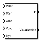
Bridge Cycloconverter Voltage Controller (Three-Phase)
RMS Voltage PI control for three-phase bridge cycloconverters
Libraries:
Simscape /
Electrical /
Control /
Converter Control
Description
The Bridge Cycloconverter Voltage Controller (Three-Phase) block implements a PI-based root-mean-square (RMS) voltage controller for three-phase bridge cycloconverters.
To convert a three-phase signal directly from a higher frequency to a lower frequency, use this block with a three-phase bridge cycloconverter. Refer to Three-Phase Bridge Cycloconverter for an example of such a conversion.
Operating Principle
The controller regulates the cycloconverter line-to-neutral RMS voltage to a given value and a given electrical frequency. The structure of the cycloconverter controller is illustrated in this diagram.

In the diagram:
The controller integrates the desired output frequency fref to produce the reference electrical angle θe_ref.
The Signal Conditioning block filters the cycloconverter line-to-neutral voltage vcyc and current icyc to produce the per-unit RMS voltage vrms_cyc and smoothed current signal icyc_lpf.
The PI Controller generates a reference phase voltage in the q-axis from the error between the desired output RMS voltage Vref and vrms_cyc.
The Inverse Park Transform block converts the reference phase voltage in dq0-coordinates to a phase voltage vabc_ref in abc-coordinates.
The Sinusoidal Power Measurement (PLL, Three-Phase) block estimates the phase angle θ of the input voltage signal vabc.
The Modulator and Bank Selector blocks create the 36 pulses to drive the cycloconverter using the reference phase voltage vabc_ref, estimated phase angle θ, and filtered cycloconverter current icyc_lpf. To generate the firing angles, the controller uses the cosine wave crossing method.
This diagram shows the signal conditioning logic.

In the diagram:
The Park Transform blocks convert the measured cycloconverter voltage vcyc and current icyc into d- and q-axis components (vd,vq,id,iq) using the reference electrical angle θe_ref.
The Low-Pass Filter (LPF) blocks remove the high-frequency noise from each of the d- and q-axis voltage and currents to produce the filtered components (vd_lpf, vq_lpf, id_lpf, iq_lpf).
The block calculates the cycloconverter per-unit RMS voltage vrms_cyc by taking the squared sum of the dq components, dividing by , and finally converting from SI to per-unit representation.
The Inverse Park Transform converts the dq filtered current back to the abc-axis and outputs it as icyc_lpf.
The cycloconverter reference line-to-neutral rms voltage output is given in per-unit representation.
Visualization
The block outputs a bus containing six signals for visualization:
The estimated phase angle θ of the input voltage signal vabc
The desired RMS voltage Vref of the output signal
The reference phase voltages vabc_ref of the desired output signal
The filtered line-to-neutral cycloconverter RMS voltage vrms_cyc
The filtered cycloconverter phase currents icyc_lpf
The filtered cycloconverter phase voltages vcyc_lpf
Examples

Three-Phase Bridge Cycloconverter
A three-phase bridge cycloconverter. The cycloconverter consists of 36 thyristors and has the capacity to lower the frequency of the input voltage. The Control subsystem implements the cycloconverter RMS voltage control. It also provides pulse generation for the firing of the thyristors. The Visualization subsystem contains scopes that allow you to see the simulation results. The simulation time, t, is 1 second. The load increases when Load1 switches on at t = 0.75 seconds.
Ports
Input
Output
Parameters
References
[1] Chen, H., M. H. Johnson, and D. C. Aliprantis. "Low-frequency AC transmission for offshore wind power." IEEE Transactions on Power Delivery. Vol. 28, Number 4, 2013, pp. 2236–2244.
Extended Capabilities
Version History
Introduced in R2017b