Average-Value DC-DC Converter
Average-value DC-DC converter
Libraries:
Simscape /
Electrical /
Semiconductors & Converters /
Converters
Description
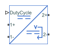
The Average-Value DC-DC Converter block represents a controlled average-value DC-DC converter. You can program the block as a buck converter, boost converter, or buck-boost converter by providing the duty cycle. The diagram shows the equivalent circuit for the block with duty cycle as input. The converter contains a controlled current source and a controlled voltage source. Use the duty cycle, the current reference, or the voltage reference ports as control input to convert the electrical energy between the connected components on either side of the converter.

Equations
If you set the Control input parameter to Duty
cycle, the input current and output voltage are a function of the
duty cycle and depend on the converter type.
Voltage and Current Equations
| Converter Type | Output Voltage, | Input Current, |
|---|---|---|
| Buck | ||
| Boost | ||
| Buck-Boost |
If you set the Control input parameter to Current
reference, the converter sets the output current and it computes
the voltage.
Similarly, if you set the Control input parameter to
Voltage reference, the converter sets the output
voltage and it computes the current.
Variables
Since R2025a
To enable the Initial Targets and Nominal
Values sections, set the Implementation mode
parameter to Average value.
To set the priority and initial target values for the block variables before simulation, use the Initial Targets section in the block dialog box or Property Inspector. For more information, see Set Priority and Initial Target for Block Variables.
Nominal values provide a way to specify the expected magnitude of a variable in a model. Using system scaling based on nominal values increases the simulation robustness. You can specify nominal values using different sources, including the Nominal Values section in the block dialog box or Property Inspector. For more information, see System Scaling by Nominal Values.
Limitations and Assumptions
The input voltage is positive.
All converter types use the same polarity for input and output.
Examples
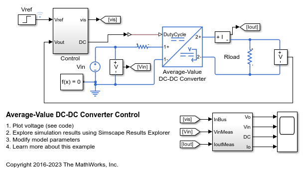
Average-Value DC-DC Converter Control
Control the output voltage of a buck-boost converter. To adjust the duty cycle, the Control subsystem uses a PI-based control algorithm. An average-value DC-DC converter model is used to speed up the simulation. The input voltage and the system load are held constant throughout the simulation. The total simulation time (t) is 0.25 s. At t = 0.15 s, the voltage reference changes and the system switches from buck mode to boost mode.
Linearize DC-DC Converter Model
Linearize a model of a DC-DC converter using averaged switching or an average-value converter.
Ports
Conserving
Parameters
Extended Capabilities
Version History
Introduced in R2018bSee Also
Average-Value Chopper | Average-Value Inverter (Three-Phase) | Average-Value Rectifier (Three-Phase) | Bidirectional DC-DC Converter | Buck Converter | Buck-Boost Converter | Boost Converter | Converter (Three-Phase) | DC-DC Converter | Rectifier (Three-Phase) | Three-Level Converter (Three-Phase)