Representing Solid Inertia
Inertia is a basic attribute of anything you might construe as a body. It is a resistance to a change in one’s state of motion, and, equivalently, a measure of the force or torque needed to induce a certain acceleration. Unlike other solid attributes, such as geometry or color, it is strictly required for the simulation of a multibody dynamics model. For more information about multibody dynamics simulations, see Multibody Dynamics. In particular, the ends of a joint—its frames—must each connect to an inertia, which is to say that where motion is allowed, there must exist an inertia for an applied force or torque to act upon.
Representing Inertias
You can model an inertia element in isolation, without the intent to represent a body. Such inertias are useful, for example, when simulating the vibrations induced by a clump of mud on a rotating automobile wheel. The clump is separate from the wheel body and you can model it as such. In addition, its geometry and color are in this case trivial details and you can disregard them for modeling purposes. In so doing, you treat the clump as a plain inertia—one lacking any attributes other than inertia.
Isolated plain inertias are uncommon in a model. Generally, you account for inertia in the course of modeling a complete body—something with geometry and color, like a wing in the flapping wing mechanism discussed in Modeling Bodies. You start with a concept of the body, model that body as a collection of solids, and specify the attributes of those solids to obtain a complete representation of the body. Solids are the things that you model and inertia merely one of their attributes.
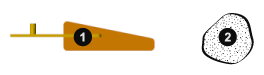
A Body (1) and a Plain Inertia (2)
Relevant Blocks
You add inertia to a model using blocks from the Body Elements library. Relevant blocks include the solid blocks, Inertia, and those in the Variable Mass sublibrary. You can model a complete solid or a plain inertia. Either can have fixed or variable inertia parameters, though the exact parameterization, and therefore the type of solid or inertia, depends on the block. The term “solid” is used here to denote an element whose attributes extend beyond merely inertia and the term “inertia,” when used to refer to an element, one whose attributes encompass only inertia.
Fixed Solids. Use the solid blocks when modeling solids and the bodies they comprise. These blocks enable you to specify geometry and color, key attributes if solid visualization is important to you. They also enable you to have the less accessible parameters of rotational inertia automatically computed from the solid geometry and either mass or mass density. Even in cases where geometry and color are superfluous details, the solid blocks are often the most convenient means of specifying inertia. Note that the geometry and inertia parameters of the solid blocks are strictly constant. To model solids with either as a variable attribute, you must use blocks from the Variable Mass sublibrary.
Variable Solids. Use the solid blocks in the Body Elements > Variable Mass library to model complete solids with variable inertia parameters, such as mass, and inertia-dependent dimensions, such as length and radius, that can vary dynamically with the inertia inputs. Blocks that represent solids are identified as such by having the word Solid in their names—for example, Variable Cylindrical Solid and Variable Brick Solid. These blocks differ from the solid blocks in the parent library in that one or more inertia parameters can change, and from the General Variable Mass block in that they possess geometry and color.
Fixed Inertias. Use the Inertia block as a means of adjusting the inertia of a solid or body. Geometry and color are considered irrelevant for modeling purposes. You can subtract a mass to account for the existence of a hollow region, such as an empty compartment in a vessel originally modeled without one. You can also add a mass to account for the presence of small disturbances, such as the clumps of mud that sometimes linger on an automobile wheel. Note that you can make the same adjustments, sometimes more intuitively, using the more sophisticated solid blocks.
Variable Inertias. Reserve the General Variable Mass block for the special cases in which mass, center of mass, or the inertia tensor must change in response to some input—often just time itself—without making assumptions about solid geometry. You can model events such as the scooping of a load by a backhoe (an example of a variable mass), the movement of an occupant on a manlift (an example of a variable center of mass), and the sloshing of a fluid load contained in a tank truck (an example of a variable inertia tensor).
Inertia Parameters
Solid blocks have access to geometry data and can therefore calculate inertia parameters given a shape and a mass. This feature greatly reduces the number of parameters that you must specify in a model. Automatic inertia calculation is always enabled in solid blocks, such as Brick Solid and Cylindrical Solid. It is enabled by default in the solid blocks, meaning that you can change this setting.
You can also specify the inertia parameters explicitly, for example, to precisely capture the inertia of a body for which you have only a rough geometry. An example is an odd-shaped link, for example one typical of a backhoe excavator arm, that you have approximated using a simple Brick Solid block shape. The solid geometry is in this case not very accurate and you may prefer to specify the inertia parameters using CAD (or other) data.
If you choose to specify inertia explicitly, there are two parameterizations that you can use. One enables you to treat the solid or inertia as a point mass: the Point Mass parameterization. The other enables you to treat the solid or inertia as a distributed mass: the Custom parameterization. You can select the option best suited for your application using the Inertia > Type dropdown list.
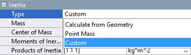
Note that the Point Mass and Custom parameterizations are available only in those blocks that support the explicit specification of inertia. The variable solid blocks in the Body Elements > Variable Mass library do not provide either. In those blocks, the center of mass and inertia tensor are strictly constrained to the solid geometry and density and are, for this reason, always automatically calculated during simulation.
The Point Mass Approximation. A point mass is an approximation that has as its only inertial parameters the center of mass and the total mass—a measure of translational inertia and therefore of the resistance to a sudden change in translational velocity. Rotational inertia is assumed negligible and is ignored. The location of the center of mass can vary with respect to the origin of the local reference frame.

Custom Mass Distributions. A distributed mass is a more general representation of inertia. It has among its inertial parameters not only the total mass and center of mass, but also the moments of inertia, and products of inertia. The moments and products of inertia comprise what is known as the inertia tensor or matrix. Together, these parameters suffice to completely describe, from a multibody modeling perspective, the distribution of a mass in space.

A Note on Joint Connections. Use caution when connecting inertias with zero moments of inertia, such as point masses, to joints with rotational degrees of freedom—those composed at least in part of revolute or spherical joint primitives. The combined moment of inertia about the rotational axes of the joint must be nonzero on each side. The reason for this is simple: the angular acceleration about an axis becomes infinite regardless of the torque applied if the moment of inertia about that axis is zero. This behavior is not physical and is disallowed in a model.
Reference Frames
Blocks in the Body Elements library have reference frame ports that you connect to resolve the placement of the respective elements—solids, inertias—in the context of a model. The reference frames are a rigid part of those elements and naturally move with them as a unit. They are used, directly or indirectly, to define the inertias and, in solids, the geometries of the elements.
If the concept of a frame is foreign to you, see Working with Frames. Succinctly, a frame is an axis triad much like a Cartesian coordinate system. It has a position and orientation that you can define using the frame creation interface of the Solid block or the parameters of the Rigid Transform block. All positions and orientations in a model—of solids, inertias, joints and constraints, forces and torques, sensors—are defined through frames.
Reference Frame of a Solid
Visualization Options
You can visualize solids and inertias in a model. The type of visualization that you get depends on the block that you use. Solid blocks, including those from the Body Elements > Variable Mass library, enable you to visualize their respective elements using the geometries that you specify. You can also visualize the solid using a simple graphic marker such as a sphere—for example, to highlight its position in cases where geometry is known to be inaccurate.
Inertias lack geometry and color and naturally do not support geometry-based visualization. You must visualize such elements using alternative means. If the element is associated with a General Variable Mass block, you can use the same graphic markers provided in the solid blocks or an equivalent inertia ellipsoid—a shape whose dimensions depend directly on the inertia parameters that you specify. If the element is associated with an Inertia block, you can use the markers of the solid blocks or an inertia icon.
For more information on visualization, see Visualize a Model and Its Components.
Try It: Add an Inertia to a Model
Add a plain fixed inertia to a double-pendulum model, position it at the free end of the outer link, and set its mass to 25 g using the Point Mass parameterization:
At the MATLAB® command prompt, enter
openExample("sm/DocDoublePendulumModelExample"). A model of a double-pendulum opens up. In it are three Simulink Subsystem blocks, each representing a body. Save the model under a different name in a convenient folder.From the Body Elements library, add an Inertia block and connect its reference frame port (labeled R) to the rightmost frame port of the
Binary Link A1block. The frame associated with this port is located at the free end of the double pendulum.In the Inertia block dialog box, set the Mass parameter to
25 g—a value roughly equivalent to a quarter of the mass of a binary link (130 g). ThePoint Massparameterization in this block enables you to ignore the rotational inertia parameters.Simulate the model. Multibody Explorer opens with a dynamic visualization of your updated double-pendulum. Notice the inertia icon used to denote the location of your inertia element.

See “Try It: Specify a Custom Inertia” for an example showing how to specify the parameters of a Custom inertia.
Compounding Solids and Inertias
As solid shapes grow in complexity, inertia parameters become increasingly cumbersome to specify and a different approach may suit you better: compounding. You can conceive of a complex solid or inertia as a collection of simpler elements and specify their inertia parameters explicitly, if using the Inertia or General Variable Mass block, or configure them for automatic calculation, if using a solid block.
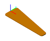
When you rigidly connect the simpler elements—via frame connection lines and, if needed, Rigid Transform blocks—you obtain an aggregate whose inertia properties mirror those of the complex solid or inertia you intended to represent. The binary link shown in the figure serves as an example. You can divide the link into three sections, represent each section using a separate block, and connect the respective reference frames using appropriate rigid transforms.
![]()
For an example showing how to specify the geometry of a binary link through compounding, see Create a Compound Geometry.
Negative Inertia as Subtraction
There is no requirement in the Simscape™ Multibody™ environment that the inertia parameters be positive. This includes the mass and moments of inertia, both parameters that in the physical world are strictly positive. Negative inertias enable you to model compound inertias with hollow sections by subtraction and are therefore useful in certain models.
The binary link again serves as an example. You can represent the link as a single piece without holes using one block, and subtract from its ends the inertias of the holes using additional blocks. As before, you must use rigid transforms to properly position the inertia reference frames relative to each other.
![]()
For an example, showing how to specify an inertia by compounding, see Create a Compound Inertia.