Link to Requirements Modeled in Simulink
This example shows how to link between verification subsystems and models. You can use verification subsystems to model functional requirements and verify them in simulation. Traceability between the verification and implementation models allow you to summarize analysis and test results in the Requirements Editor.
Open Example Models
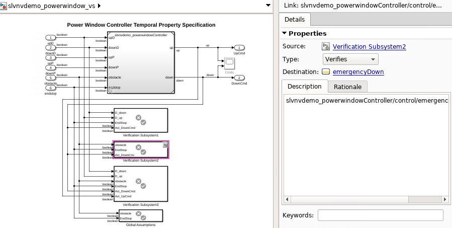
Open the slvnvdemo_powerwindow_vs model.
open_system("slvnvdemo_powerwindow_vs")The verification model specifies properties and requirements for slvnvdemo_powerwindowController. The verification subsystems include logic that verifies system behavior when an obstacle is detected:
Obstacle Response: When an obstacle is detected, the controller shall give the
downcommand for 1 second.
The requirement is modeled in Verification Subsystem2.
open_system("slvnvdemo_powerwindow_vs/Verification Subsystem2")In the design model, the obstacle response is implemented in the emergencyDown state:
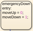
Link from Verification to Design Model
Create a link from Verification Subsystem2 to the emergencyDown state:
In the
slvnvdemo_powerwindow_vsmodel, double-click on theslvnvdemo_powerwindowControllermodel reference block.Open the
controlchart by double-clicking it.In the
controlchart, right-click the emergencyDown state and select Requirements > Select for Linking with Simulink.In the
slvnvdemo_powerwindow_vsmodel, right-click theVerification Subsystem2block and select Requirements > Add Link to Selected Object.In the
slvnvdemo_powerwindow_vsmodel, open the Requirements Manager app. In the Requirements pane, set View toLinks.In the Requirement links pane, select the link. In the Property Inspector, under Properties, set the lnk type to
Verifies.
You can also select a web site from the following list:
Americas
- América Latina (Español)
- Canada (English)
- United States (English)
Europe
- Belgium (English)
- Denmark (English)
- Deutschland (Deutsch)
- España (Español)
- Finland (English)
- France (Français)
- Ireland (English)
- Italia (Italiano)
- Luxembourg (English)
- Netherlands (English)
- Norway (English)
- Österreich (Deutsch)
- Portugal (English)
- Sweden (English)
- Switzerland
- United Kingdom (English)