Detect Design Errors in AUTOSAR Software Component Model
The AUTOSAR standard defines Basic Software (BSW) services that run in the AUTOSAR run-time environment. The services include NVRAM Manager (NvM) Diagnostic Event Manager (Dem), and Function Inhibition Manager (FiM) services. The following example shows how to use Simulink® Design Verifier™ to run design error checks on the AUTOSAR component model.
Prepare the Model
Open the AUTOSAR software component. This example uses AUTOSAR Simulink model autosar_bsw_monitor.
model = 'autosar_bsw_monitor';
open_system(model);
Monitor component autosar_bsw_monitor contains a call to the Dem service interface DiagnosticMonitor and four calls to the Dem service interface DiagnosticInfo. The four DiagnosticInfo calls are implemented using the Basic Software library block DiagnosticInfoCaller (AUTOSAR Blockset). Each block is configured to call the DiagnosticInfo operation GetEventFailed. The GetEventFailed calls use client ports TPS1StuckLow, TPS1StuckHigh, TPS2StuckLow, and TPS2StuckHigh.
Perform Design Error Detection Analysis
To detect the design errors in the above component model, configure the Design Verifier options as follows:
opts = sldvoptions;
opts.Mode = "DesignErrorDetection";
opts.DetectDeadLogic = 'on';
opts.DetectActiveLogic = 'on';
opts.DefectChecker = "off";
Analyze the model.
[ status, files ] = sldvrun('autosar_bsw_monitor', opts, true);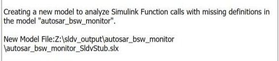
The Simulink Design Verifier Results Summary window indicates that an analysis harness model autosar_bsw_monitor_SldvStub is created. You can also generate the same analysis harness model using sldvextract function.
Review the Analysis Results
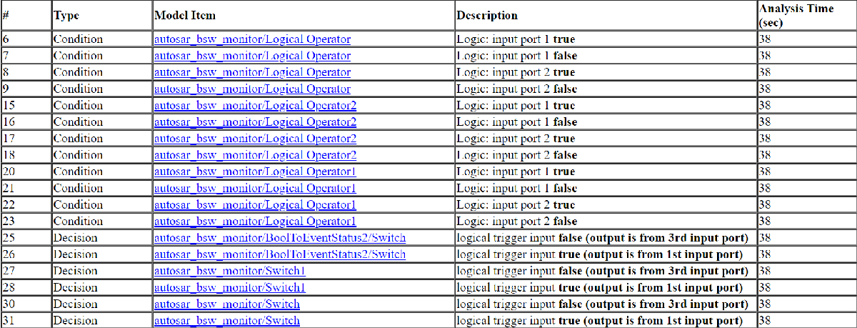
The Simulink Design Verifier Results Summary window shows that 18 of 18 objectives are active logic in the model.
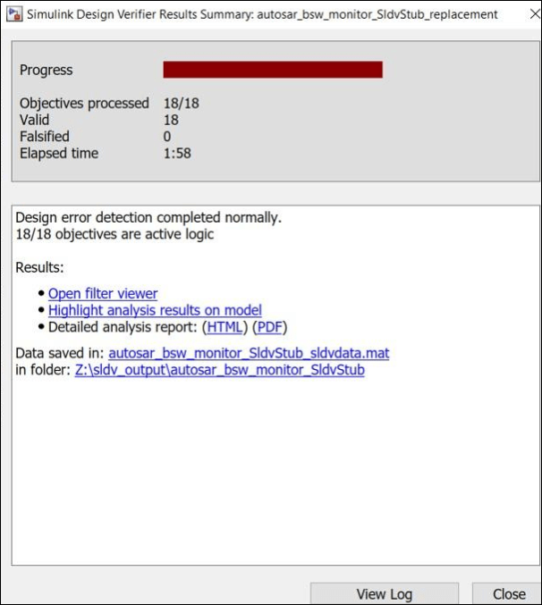
To view the detailed analysis report, click the HTML link in the Results Summary window. The Design Error Detection Objectives Status section includes the Active Logic objectives statuses for the model.
The analysis report also captures information about the analysis harness for analyzing the model in the Analysis Harness Information section. The Stubbed Simulink Functions for Analysis section in the Analysis Harness Information section lists the stubbed Simulink functions.

Note that Simulink Design Verifier assumes that the output of stubbed Simulink Functions is held when the functions are invoked multiple times in a single step.