Disturbance Rejection Goal
Purpose
Attenuate disturbances at particular locations and in particular frequency bands, when using Control System Tuner.
Description
Disturbance Rejection Goal specifies the minimum attenuation of a disturbance injected at a specified location in a control system.
When you use this tuning goal, the software attempts to tune the system so that the attenuation of a disturbance at the specified location exceeds the minimum attenuation factor you specify. This attenuation factor is the ratio between the open- and closed-loop sensitivities to the disturbance, and is a function of frequency.
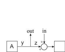
The following diagram illustrates how the attenuation factor is calculated. Suppose you
specify a location in your control system, y, which is the output of a
block A. In that case, the software calculates the closed-loop
sensitivity at out to a signal injected at in. The
software also calculates the sensitivity with the control loop opened at the location
z.
To specify a Disturbance Rejection Goal, you specify one or more locations at which to attenuate disturbance. You also provide the frequency-dependent minimum attenuation factor as a numeric LTI model. You can achieve disturbance attenuation only inside the control bandwidth. The loop gain must be larger than one for the disturbance to be attenuated (attenuation factor > 1).
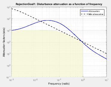
When you create a tuning goal in Control System Tuner, a tuning-goal plot is generated. The dotted line shows the gain profile you specify. The shaded area on the plot represents the region in the frequency domain where the tuning goal is not satisfied. The solid line is the current corresponding response of your system.
If you prefer to specify sensitivity to disturbance at a location, rather than disturbance attenuation, you can use Sensitivity Goal.
Creation
In the Tuning tab of Control System Tuner, select New Goal > Disturbance rejection to create a Disturbance Rejection Goal.
Command-Line Equivalent
When tuning control systems at the command line, use TuningGoal.Rejection to specify a disturbance rejection goal.
Disturbance Scenario
Use this section of the dialog box to specify the signal locations at which to inject the disturbance. You can also specify loop-opening locations for evaluating the tuning goal.
Inject disturbances at the following locations
Select one or more signal locations in your model at which to measure the disturbance attenuation. To constrain a SISO response, select a single-valued location. For example, to attenuate disturbance at a location named
'y', click Add signal to list and select
 'y'. To constrain a MIMO response, select multiple signals or a vector-valued signal.Evaluate disturbance rejection with the following loops open
Select one or more signal locations in your model at which to open a feedback loop for the purpose of evaluating this tuning goal. The tuning goal is evaluated against the open-loop configuration created by opening feedback loops at the locations you identify. For example, to evaluate the tuning goal with an opening at a location named
'x', click
Add signal to list and select 'x'.
Tip
To highlight any selected signal in the Simulink® model, click ![]() . To remove a signal from the input or output list, click
. To remove a signal from the input or output list, click ![]() . When you have selected multiple signals, you can reorder
them using
. When you have selected multiple signals, you can reorder
them using ![]() and
and ![]() . For more information on how to specify signal locations
for a tuning goal, see
Specify Goals for Interactive Tuning.
. For more information on how to specify signal locations
for a tuning goal, see
Specify Goals for Interactive Tuning.
Rejection Performance
Specify the minimum disturbance attenuation as a function of frequency.
Enter a SISO numeric LTI model whose magnitude represents the desired attenuation
profile as a function of frequency. For example, you can specify a smooth transfer function
(tf, zpk, or ss model). Alternatively, you can sketch a
piecewise minimum disturbance rejection using an frd model. When you do so, the software automatically maps the profile to a
smooth transfer function that approximates the desired minimum disturbance rejection. For
example, to specify an attenuation factor of 100 (40 dB) below 1 rad/s, that gradually drops
to 1 (0 dB) past 10 rad/s, enter frd([100 100 1 1],[0 1 10 100]).
If you are tuning in discrete time, you can specify the attenuation profile as a discrete-time model with the same sampling time as you use for tuning. If you specify the attenuation profile in continuous time, the tuning software discretizes it. Specifying the attenuation profile in discrete time gives you more control over the profile near the Nyquist frequency.
Options
Use this section of the dialog box to specify additional characteristics of the disturbance rejection goal.
Enforce goal in frequency range
Limit the enforcement of the tuning goal to a particular frequency band. Specify the frequency band as a row vector of the form
[min,max], expressed in frequency units of your model. For example, to create a tuning goal that applies only between 1 and 100 rad/s, enter[1,100]. By default, the tuning goal applies at all frequencies for continuous time, and up to the Nyquist frequency for discrete time.Regardless of the limits you enter, a disturbance rejection goal can only be enforced within the control bandwidth.
Equalize cross-channel effects
For multiloop or MIMO disturbance rejection requirements, the feedback channels are automatically rescaled to equalize the off-diagonal (loop interaction) terms in the open-loop transfer function. Select
Offto disable such scaling and shape the unscaled open-loop response.Apply goal to
Use this option when tuning multiple models at once, such as an array of models obtained by linearizing a Simulink model at different operating points or block-parameter values. By default, active tuning goals are enforced for all models. To enforce a tuning requirement for a subset of models in an array, select Only Models. Then, enter the array indices of the models for which the goal is enforced. For example, suppose you want to apply the tuning goal to the second, third, and fourth models in a model array. To restrict enforcement of the requirement, enter
2:4in the Only Models text box.For more information about tuning for multiple models, see Robust Tuning Approaches (Robust Control Toolbox).
Algorithms
Evaluating Tuning Goals
When you tune a control system, the software converts each tuning goal into a normalized scalar value f(x). Here, x is the vector of free (tunable) parameters in the control system. The software then adjusts the parameter values to minimize f(x) or to drive f(x) below 1 if the tuning goal is a hard constraint.
For Disturbance Rejection Goal, f(x) is given by:
or its discrete-time equivalent. Here,
S(jω,x) is the closed-loop
sensitivity function measured at the disturbance location. Ω is the frequency interval
over which the requirement is enforced, specified in the Enforce goal in
frequency range field. WS is a
frequency weighting function derived from the attenuation profile you specify. The gains
of WS and the specified profile roughly match
for gain values ranging from –20 dB to 60 dB. For numerical reasons, the weighting
function levels off outside this range, unless the specified gain profile changes slope
outside this range. This adjustment is called regularization.
Because poles of WS close to
s = 0 or s = Inf might lead to
poor numeric conditioning for tuning, it is not recommended to specify loop shapes with
very low-frequency or very high-frequency dynamics. For more information about
regularization and its effects, see Visualize Tuning Goals.
Implicit Constraints
This tuning goal imposes an implicit stability constraint on the closed-loop sensitivity function measured at the specified, evaluated with loops opened at the specified loop-opening locations. The dynamics affected by this implicit constraint are the stabilized dynamics for this tuning goal. The Minimum decay rate and Maximum natural frequency tuning options control the lower and upper bounds on these implicitly constrained dynamics. If the optimization fails to meet the default bounds, or if the default bounds conflict with other requirements, on the Tuning tab, use Tuning Options to change the defaults.